+86 29 8881 0979

NEWS

Exploring the science of extremely low frequency phenomena.

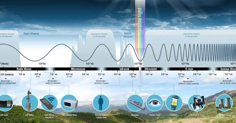
Exploring extremely low frequency (ELF, 3-300Hz) phenomena involves analyzing natural sources like lightning-induced pulses (1-100Hz, 100kV/m fields) and artificial systems (e.g., submarine comms at 70-150Hz, 200km wavelength), using magnetometers for field measurements and underground antennas to study propagation through conductive media like Earth’s crust. What Are ELF Waves? Extremely Low Frequency (ELF) waves are electromagnetic […]

Exploring the science of extremely low frequency phenomena. Read More »

Wavegude-to-Coaxial-Adapter

Guide on waveguide to coaxial adapters and benefits

Waveguide-to-coaxial adapters, such as WR-90 (8-12GHz) to RG-58 (50Ω), facilitate RF signal transfer with <0.3dB insertion loss and VSWR <1.2. Constructed from stainless steel (-55°C to 125°C), they handle 50W+ power, ensuring low-loss, reliable connections in microwave systems like radar or test setups. What They Are and How They Work In practice, this is critical

Guide on waveguide to coaxial adapters and benefits Read More »

Why do satellites use high frequency

Satellites use high frequencies (e.g., Ku/Ka bands, 12–40GHz) for wider bandwidth (hundreds of MHz vs. tens in L-band), enabling higher data rates; shorter wavelengths allow compact antennas, reducing launch weight while minimizing terrestrial interference. Why High Frequency Matters High-frequency bands, typically classified as those above 3 GHz, such as Ku-band (12–18 GHz) and Ka-band (26.5–40

Why do satellites use high frequency Read More »

What is the difference between Yagi and Omni antenna

Yagi antennas are directional, with a driven element, reflector, and directors, offering 10–15dBi gain at 2.4GHz for focused point-to-point links. Omni antennas radiate uniformly horizontally (2–5dBi gain), suited for area coverage; Yagi typically operates 400MHz–6GHz, Omni 30MHz–6GHz, differing in pattern and use case. How They Send and Receive Signals A Yagi antenna, like a flashlight,

What is the difference between Yagi and Omni antenna Read More »

What is the function of coupler antenna

Coupler antennas integrate signal routing and isolation functions, enabling power division (e.g., 10–20dB splits) or sampling (insertion loss <0.3dB) between transmit/receive paths while maintaining >25dB isolation at 2–18GHz to minimize interference, optimizing RF system efficiency. Connecting Two Devices Wirelessly A common challenge in RF systems is efficiently transferring a signal from a primary transmitter to

What is the function of coupler antenna Read More »

What is the limit of C-Band

The C-band, defined by ITU as 4-8 GHz, faces practical limits: rain fade at 100mm/h induces 0.5-1dB/km loss at 6GHz, impacting satellite links (uplink 5.925-6.425GHz, downlink 4.6-5.0GHz). Antenna gain (30-40 dBi for 3-6m dishes) and LNA noise figures (0.5-1.5dB) constrain sensitivity, while physical size limits high-gain use in compact systems. Defining C-Band Frequency Range The

What is the limit of C-Band Read More »

How do satellite antennas work

Satellite antennas operate via parabolic reflectors that focus electromagnetic waves onto a feed horn; a 3-meter diameter dish in Ku-band (12-18GHz) achieves ~40dBi gain, directing signals toward satellites. During transmission, electrical signals convert to waves at the feed, reflected into parallel beams by the parabola; reception reverses this, focusing incoming waves (error <0.1° in azimuth/elevation)

How do satellite antennas work Read More »

How do you test a directional coupler

To test a directional coupler, connect it to a signal generator (output: +10dBm, 2-4GHz) and spectrum analyzer. Measure input power (Pin) at the main port, coupled power (Pcouple) at the coupled port, and isolated port power (Piso). Calculate insertion loss (Pin-Pthru, typical 0.5-2dB), isolation (Pin-Piso ≥20dB), and directivity (Pcouple-Piso ≥30dB) to validate performance. Measure Insertion

How do you test a directional coupler Read More »

Introducing the High Power Differential Phase Shift WG Circulator

The High Power Differential Phase Shift WG Circulator operates in X-band (8-12 GHz), supporting 500W peak input power with <0.5 dB insertion loss and >40 dB isolation. Its optimized ferrite structure minimizes phase error to ±2°, ensuring stable signal routing in high-power radar systems. What It Is and How It Works A High Power Differential

Introducing the High Power Differential Phase Shift WG Circulator Read More »

Ka-Band 4-Port Diplexer with Circular Polarization for Antenna Networks

The Ka-band 4-port duplexer supports circular polarization and is suitable for antenna networks. The frequency range is usually 26.5 to 40 GHz. It can achieve efficient merging and separation of multi-path signals, ensuring a transmission rate of more than 10 Gbps. The polarization direction must be accurately calibrated during installation to optimize performance. Ka-band Characteristics

Ka-Band 4-Port Diplexer with Circular Polarization for Antenna Networks Read More »

Scroll to Top
Blank Form (#3)