+86 29 8881 0979

default

Wavange Compatibility, Fast Assembly, Signal Integrity

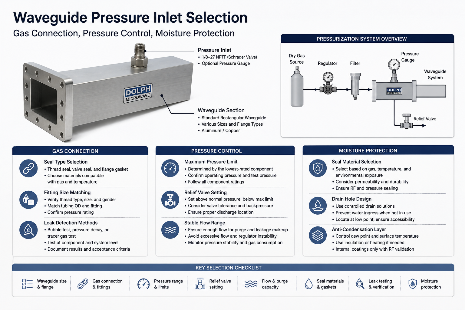
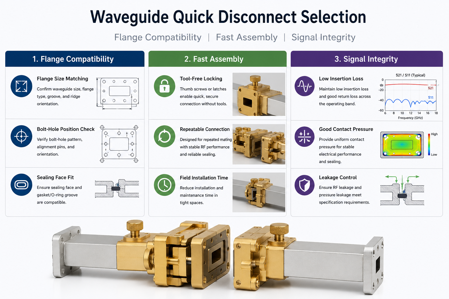
A waveguide quick disconnect should not be selected only because it can be opened without conventional flange bolts. A reliable assembly must perform three functions at the same time: match the existing waveguide interface, create consistent mechanical contact, and preserve the required RF and environmental performance after repeated connections. The word “quick” describes the locking […]

Wavange Compatibility, Fast Assembly, Signal Integrity Read More »

Waveguide Pressure Inlet Selection | Gas Connection, Pressure Control, Moisture Protection<

A waveguide pressure inlet should be selected as part of a complete pressurization system, not as an isolated threaded port. The inlet must match the pressurizing gas connection, waveguide size, flange interface, seal arrangement, operating pressure, relief path, tubing capacity, and moisture-control method. For most microwave transmission systems, “gas connection” refers to a connection for

Waveguide Pressure Inlet Selection | Gas Connection, Pressure Control, Moisture Protection< Read More »

Waveguide Bulkhead Feedthrough Selection | Barrier Mounting, Pressure Sealing, Flange Alignment

A waveguide bulkhead feedthrough should not be selected by waveguide size alone. It is simultaneously an RF transmission interface, a mechanical penetration through a wall or enclosure, and—in many installations—a controlled pressure boundary. A feedthrough that fits the nominal WR size can still fail in service if the wall thickness is wrong, the cutout interferes

Waveguide Bulkhead Feedthrough Selection | Barrier Mounting, Pressure Sealing, Flange Alignment Read More »

Waveguide Flange Size Guide | EIA Standard, IEC Types, Gasket Fit

When selecting waveguide flanges, the biggest pitfall I’ve encountered is that for the same WR model, the EIA and IEC systems share nearly identical inner widths but differ completely in bolt hole patterns, sealing grooves, and fit classes. Once, when sourcing parts for a satellite ground station, the client specified IEC standard UG-385/U, but I

Waveguide Flange Size Guide | EIA Standard, IEC Types, Gasket Fit Read More »

Ku-Band Satellite Antenna Selection | Weather Fade, High Throughput, Dish Size

Ku-band procurement should lock onto 1.2-meter antennas to reserve a 5dB rain fade margin. HTS requires LNBs with a 0.2dB low noise figure. Utilizing AGC technology for compensation and fine-tuning polarization angles can withstand heavy rainfall of 30mm/h, ensuring 99.9% availability for high-throughput systems. Weather Fade Operating in the 12-18 GHz range, Ku-band wavelengths are

Ku-Band Satellite Antenna Selection | Weather Fade, High Throughput, Dish Size Read More »

Flat Panel Satellite Antenna Technology | Metamaterials, Electronic Steering, LEO

Flat-panel satellite antennas utilize metamaterials for electronically controlled scanning, with a thickness of only 5cm and millisecond-level switching, perfectly adapted for LEO. Its ±60° wide-angle tracking and Ku/Ka band coverage ensure high-speed “Comms-on-the-move” (COTM). It requires software-defined beam orientation to achieve a gain of over 35dBi, reducing wind resistance and maintenance costs by 40% compared

Flat Panel Satellite Antenna Technology | Metamaterials, Electronic Steering, LEO Read More »

Log Periodic Antenna Working Principle Explained | Broadband, Self-Similar Structure

Log-periodic antennas rely on self-similar structures to achieve extremely wideband coverage, such as from 30MHz to 3GHz. During fabrication, multiple dipoles must be arranged proportionally, and the scaling factor for the length and spacing of adjacent elements is usually set to 0.85. In operation, the signal is fed into the shortest element at the very

Log Periodic Antenna Working Principle Explained | Broadband, Self-Similar Structure Read More »

Log Periodic Antenna Design Guide | Frequency Range, Gain, Structure

Designing a log-periodic antenna requires first determining the coverage frequency band, with its operating frequency typically ranging between 30 MHz and 3 GHz. Its structure consists of multiple parallel dipoles with gradually changing lengths. During operation, the half-wavelength corresponding to the lowest operating frequency must first be calculated and used as the physical dimension of

Log Periodic Antenna Design Guide | Frequency Range, Gain, Structure Read More »

Custom IoT Antenna Solutions | Power, Size, Connectivity

By precisely controlling return loss below -10dB, customized antennas significantly enhance signal transmission efficiency by 20% within a miniature size and effectively reduce system power consumption by 15%, thereby ensuring superior connectivity stability and authoritative reliability for multi-band connections in complex industrial environments. Power Efficiency Through precise impedance matching, customized antennas control the Voltage Standing

Custom IoT Antenna Solutions | Power, Size, Connectivity Read More »

Custom 5G Antenna Solutions | High Bandwidth, MIMO, Latency

Leveraging our deep accumulation of RF technology, we provide customized 5G antenna solutions. By utilizing an advanced 4×4 MIMO architecture and supporting millimeter-wave (mmWave) bands, we achieve peak throughput exceeding 10Gbps and extreme latency below 1ms, ensuring absolute reliability and data integrity in high-bandwidth industrial interconnection scenarios. High Bandwidth Optimization In the 5G Sub-6GHz band,

Custom 5G Antenna Solutions | High Bandwidth, MIMO, Latency Read More »

Scroll to Top
Blank Form (#3)