+86 29 8881 0979

Author name: Dolph

How to choose the right waveguide component for 5G antennas

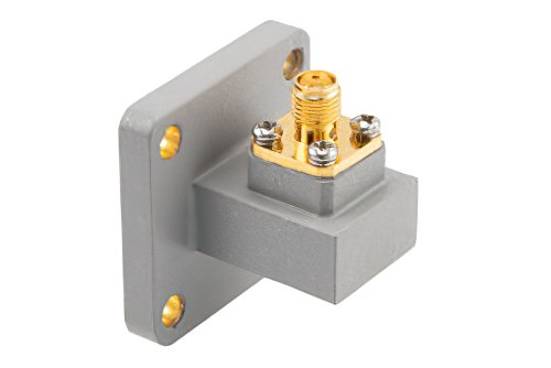
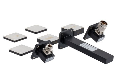
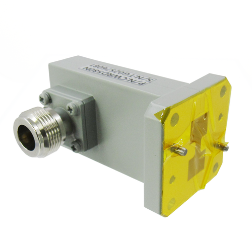
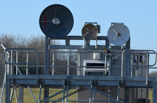
Select waveguide components by evaluating frequency bands (e.g., 24-40 GHz for mmWave), insertion loss (<0.1 dB preferred), and power handling (e.g., 50W average). Ensure precise impedance matching and material compatibility (e.g., aluminum or brass) for optimal 5G antenna performance. Understanding 5G Frequency Bands Selecting the right waveguide component starts with a solid grasp of 5G […]

How to choose the right waveguide component for 5G antennas Read More »

How to optimize waveguide transfer switches for minimal signal loss

Optimize waveguide transfer switches by using precision-machined components with surface roughness below 0.1 µm, ensuring perfect alignment to minimize insertion loss to under 0.1 dB and VSWR below 1.05 through rigorous vector network analyzer testing. Understanding Waveguide Switch Basics A typical high-performance switch operating in the 18–40 GHz range might exhibit an insertion loss of

How to optimize waveguide transfer switches for minimal signal loss Read More »

What are the 7 essential tools for waveguide assembly maintenance

Essential tools for waveguide assembly maintenance include VNA (0.05dB accuracy), torque wrenches (5-50 in-lb), flange alignment pins (0.001″ tolerance), waveguide pressure testers (up to 50 psi), dielectric grease (10^12 Ω·cm), RF leak detectors (1mW sensitivity), and precision gap gauges (0.001-0.010″). ​​Basic Cleaning Brushes​ Waveguide assemblies operate in environments where even ​​0.1mm of debris​​ can cause

What are the 7 essential tools for waveguide assembly maintenance Read More »

Top 7 applications of waveguide assemblies in radar technology

Waveguide assemblies are critical in radar systems for high-power signal transmission, enabling precise targeting in military radars (up to 95% efficiency), weather monitoring (GHz-range frequencies), aviation navigation (low-loss <0.1dB/m), satellite communications (Ka-band 26.5-40GHz), maritime surveillance (resistant to corrosion), automotive collision avoidance (77GHz mmWave), and phased array radars (phase-stable beamforming). Their precision machining ensures minimal signal

Top 7 applications of waveguide assemblies in radar technology Read More »

Custom Open Ended Waveguide Probes | Frequency Range 18-110GHz​

Custom open-ended waveguide probes operate from ​​18-110 GHz​​, offering ​​<1.5:1 VSWR​​ and ​​<0.3 dB insertion loss​​ for precise millimeter-wave measurements. These probes feature ​​WR-10 to WR-8 flanges​​ and require ​​λ/4 waveguide alignment​​ for optimal performance. Ideal for ​​near-field testing and antenna characterization​​, they support ​​TE10 mode propagation​​ with ​​±0.1 mm positional accuracy​​ for high-frequency applications.

Custom Open Ended Waveguide Probes | Frequency Range 18-110GHz​ Read More »

Waveguide-SMA vs. Coaxial Adapters | 3 Critical Differences​

Waveguide-SMA and coaxial adapters differ in frequency range, power handling, and insertion loss. Waveguide adapters typically handle 18-110 GHz with <0.2 dB loss, while SMA coaxial versions cover DC-18 GHz but sustain higher losses (0.5 dB). For millimeter-wave applications above 40 GHz, waveguide adapters provide better performance with VSWR <1.2:1, whereas SMA connectors degrade to

Waveguide-SMA vs. Coaxial Adapters | 3 Critical Differences​ Read More »

SMA to Waveguide Adapters | 5 Key Specifications You Need to Know​

When selecting SMA-to-waveguide adapters, prioritize ​​frequency range​​ (e.g., 18–26.5GHz for WR-42), ​​VSWR (<1.25:1)​​, and ​​insertion loss (<0.3dB)​​. Choose ​​gold-plated brass connectors​​ for corrosion resistance and ensure ​​0.9Nm torque​​ on SMA threads to prevent signal leakage. Verify ​​TE10 mode purity​​ with >30dB suppression of higher-order modes, and opt for ​​PTFE-loaded waveguide sections​​ to minimize ​​thermal drift

SMA to Waveguide Adapters | 5 Key Specifications You Need to Know​ Read More »

Waveguide Calibration | 5 Key Steps for Accurate RF Measurements​

For precise waveguide calibration, first ​​clean all flanges​​ with 99% isopropanol to remove particles affecting ​​0.01dB repeatability​​. Use ​​torque wrenches​​ (e.g., 12 in-lb for WR-90) on flange bolts to prevent ​​0.05dB insertion loss shifts​​. Perform ​​SOLT calibration​​ with ​​3.5mm standards​​ up to 26.5GHz, then verify with ​​±0.5dB​​ thru-line measurements at ​​23°C±1°C​​ to ensure ​​VSWR <1.15​​.

Waveguide Calibration | 5 Key Steps for Accurate RF Measurements​ Read More »

​​N-Type to Waveguide vs SMA to Waveguide | 5 Performance Differences

N-Type to waveguide adapters handle up to 18GHz with 0.3dB insertion loss, while SMA versions max at 12GHz with 0.5dB loss; N-Type’s threaded coupling provides superior vibration resistance, whereas SMA’s compact size suits space-constrained millimeter-wave applications below 6GHz. Frequency Range Limits N-type connectors typically support frequencies up to ​​18 GHz​​, while SMA connectors can handle

​​N-Type to Waveguide vs SMA to Waveguide | 5 Performance Differences Read More »

How to test antenna range

​To test antenna range, use a signal generator and spectrum analyzer, measure RSSI at 1km intervals up to 10km in open terrain, maintaining 2.4GHz/5GHz test frequencies with 5dBi gain antennas at 1m elevation, recording dBm drop-off beyond line-of-sight obstacles.  ​Choose Test Location​​ Picking the right spot for antenna testing is ​​the most critical step​​—get it

How to test antenna range Read More »

Scroll to Top
Blank Form (#3)