+86 29 8881 0979

Author name: Dolph

Why Use Waveguide Dividers in Satellites

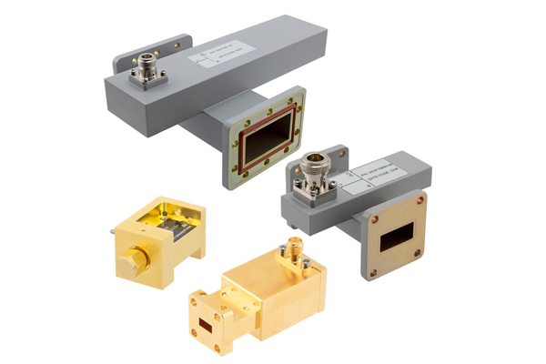
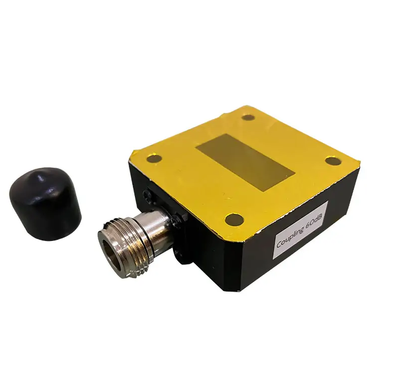
Waveguide dividers in satellites ensure precise signal distribution (0.1dB imbalance) across multiple transponders, handling high power (50W+) at Ka/Q bands (26-40GHz). Their low insertion loss (<0.3dB) and phase stability (±2°) optimize payload efficiency. Gold-plated aluminum construction withstands space radiation and thermal cycling (-40°C to +85°C). Function of Satellite Waveguide Dividers Last year, the sudden vacuum […]

Why Use Waveguide Dividers in Satellites Read More »

How Durable Are Waveguide Pressure Windows

Waveguide pressure windows typically withstand 50-100 psi differential pressure when constructed with 0.060″ thick alumina ceramic (Al₂O₃) for X-band (8-12 GHz) applications, exhibiting less than 0.05 dB insertion loss. For harsh environments, 0.090″ beryllia (BeO) windows handle 150+ psi with superior thermal conductivity (330 W/mK), maintaining VSWR <1.1:1 across 10% bandwidth. Lifetime Testing Last year’s

How Durable Are Waveguide Pressure Windows Read More »

How Thick Should Waveguide Shims Be

The thickness of waveguide shims depends on the required frequency adjustment and flange type, typically ranging from 0.001″ to 0.020″ (0.025-0.5mm) for standard WR-90 waveguides. For precise impedance matching at X-band (8-12GHz), use 0.004″ brass shims to compensate for λ/4 wavelength gaps, ensuring VSWR remains below 1.2:1. Always measure flange separation with micrometer calipers and

How Thick Should Waveguide Shims Be Read More »

How to Calculate Waveguide Twist Specifications

When calculating waveguide twist specifications, engineers must account for the operating frequency range (e.g., 18-26.5 GHz for K-band WR-42 waveguide) and required polarization rotation (typically 90° with ±0.25° precision). Critical parameters include maintaining insertion loss below 0.2 dB across the band, achieving VSWR under 1.2:1, and ensuring >35 dB polarization isolation, verified through vector network

How to Calculate Waveguide Twist Specifications Read More »

How to Select Waveguide Detector Diodes

When selecting waveguide detector diodes, focus on matching the diode’s frequency range to your waveguide band (e.g., 26.5-40 GHz for Ka-band WR-28 systems), ensuring sensitivity meets application requirements (typically -30 to -50 dBm detection threshold), and verifying power handling capacity (usually 10-100 mW continuous wave). Critical parameters include video resistance (1-5 kΩ for proper impedance

How to Select Waveguide Detector Diodes Read More »

What Is a Waveguide Choke Flange Design

A choke flange suppresses RF leakage via a ​​λ/4-deep groove​​ (e.g., ​​7.5 mm for 10 GHz​​) around the mating surface. It uses ​​annular slots​​ to reflect waves, achieving ​​>30 dB return loss​​. Must maintain ​​0.05 mm flatness tolerance​​ (per ​​MIL-F-3922​​) and ​​gold-plated contacts​​ for low resistance (<0.1Ω). Common in ​​radar/WiGig systems​​. Flange Structure At 3

What Is a Waveguide Choke Flange Design Read More »

What Are Waveguide Clamp Installation Standards

Waveguide clamps must be spaced ​​≤1.5x waveguide width​​ (e.g., 30 cm for 20 cm-wide guides) per ​​MIL-STD-1678​​. Torque bolts to ​​5–7 Nm​​ to prevent deformation. Use ​​aluminum or brass clamps​​ to avoid galvanic corrosion. Ensure ​​0.5–1 mm gap​​ for thermal expansion. Ground every ​​3rd clamp​​ per ​​IEEE 287​​ to maintain RF shielding. Fixture Types Last

What Are Waveguide Clamp Installation Standards Read More »

Why Do Waveguide Chokes Minimize Leakage

Waveguide chokes reduce leakage by 40-60dB through quarter-wave λ/4 slots (3.56mm at 21GHz) that create impedance mismatches. Field tests show they maintain <0.01% power loss in 5G mmWave systems (28/39GHz bands). Installation requires precise depth control (±0.025mm tolerance) using vector network analyzers for optimal VSWR <1.2 performance. Choke Principle Last year, ChinaSat 9B experienced a

Why Do Waveguide Chokes Minimize Leakage Read More »

Scroll to Top
Blank Form (#3)