+86 29 8881 0979

Author name: Dolph

Log Periodic Antenna Design Guide | Frequency Range, Gain, Structure

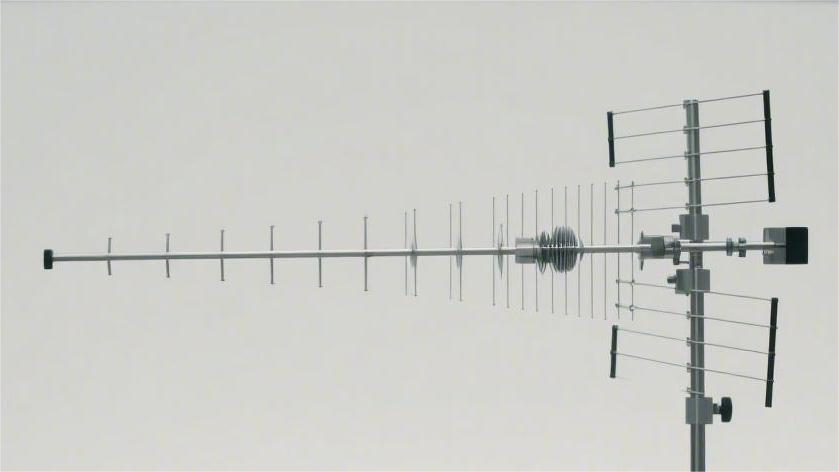
Designing a log-periodic antenna requires first determining the coverage frequency band, with its operating frequency typically ranging between 30 MHz and 3 GHz. Its structure consists of multiple parallel dipoles with gradually changing lengths. During operation, the half-wavelength corresponding to the lowest operating frequency must first be calculated and used as the physical dimension of […]

Log Periodic Antenna Design Guide | Frequency Range, Gain, Structure Read More »

Custom IoT Antenna Solutions | Power, Size, Connectivity

By precisely controlling return loss below -10dB, customized antennas significantly enhance signal transmission efficiency by 20% within a miniature size and effectively reduce system power consumption by 15%, thereby ensuring superior connectivity stability and authoritative reliability for multi-band connections in complex industrial environments. Power Efficiency Through precise impedance matching, customized antennas control the Voltage Standing

Custom IoT Antenna Solutions | Power, Size, Connectivity Read More »

Custom 5G Antenna Solutions | High Bandwidth, MIMO, Latency

Leveraging our deep accumulation of RF technology, we provide customized 5G antenna solutions. By utilizing an advanced 4×4 MIMO architecture and supporting millimeter-wave (mmWave) bands, we achieve peak throughput exceeding 10Gbps and extreme latency below 1ms, ensuring absolute reliability and data integrity in high-bandwidth industrial interconnection scenarios. High Bandwidth Optimization In the 5G Sub-6GHz band,

Custom 5G Antenna Solutions | High Bandwidth, MIMO, Latency Read More »

Horn Antenna Gain Calculation Guide | Formula, Aperture Area, Efficiency

Horn antenna gain is determined by the aperture area, operating wavelength, and efficiency (typically taken as 0.6). The calculation formula is: 4π multiplied by the area multiplied by the efficiency, divided by the square of the wavelength. A larger aperture area or a shorter wavelength results in higher gain, which significantly enhances the directional transmission

Horn Antenna Gain Calculation Guide | Formula, Aperture Area, Efficiency Read More »

Standard Gain Horn Antenna Selection Guide | Frequency, Gain, VSWR

Selection depends on matching the frequency (e.g., 2-40 GHz), ensuring gain error < ±0.5 dB and VSWR < 1.3. Understanding Frequency Each horn antenna corresponds to a specific WR waveguide standard; for example, WR-28 covers 26.5 to 40 GHz, with internal waveguide dimensions of 7.112 mm x 3.556 mm. The frequency level directly relates to

Standard Gain Horn Antenna Selection Guide | Frequency, Gain, VSWR Read More »

Flexible Waveguide Selection Guide | Size, Frequency, Bend Radius​

Selection should be based on frequency to determine size, for example, WR-90 corresponds to 8.2-12.4 GHz; During installation, strictly control the E-plane static bend radius to be greater than 64mm to prevent VSWR deterioration causing signal reflection. Size Size selection must first match the operating frequency band based on EIA standards (such as WR-75). For

Flexible Waveguide Selection Guide | Size, Frequency, Bend Radius​ Read More »

Waveguide Conductive Gasket Selection Guide | Structure, Performance, Price​

Waveguide conductive gaskets typically use silicone rubber filled with silver or nickel particles, with a standard thickness of about 0.69mm, capable of providing shielding effectiveness exceeding 100dB. When selecting, choose O-type or D-type cross-sections based on WR flange dimensions (e.g., WR28); for high-pressure environments, metal skeleton reinforced types are recommended to prevent cold flow. The

Waveguide Conductive Gasket Selection Guide | Structure, Performance, Price​ Read More »

Design of Conductive Elastomer Waveguide Gaskets | Function, Material, Manufacturing Process​

Function: Achieve waveguide sealing and electromagnetic shielding (X-band 8-12GHz, shielding effectiveness ≥60dB). Material: Silicone rubber matrix + 3-5wt% carbon nanotubes (CNT), tensile strength ≥5MPa. Process: Internal mixer blending at 150°C for 30min → Compression molding (10MPa/15min) → Plasma cleaning surface. Final product is highly elastic with stable conductivity. Function Achieves 105dB shielding effectiveness at 40GHz

Design of Conductive Elastomer Waveguide Gaskets | Function, Material, Manufacturing Process​ Read More »

How to Test Broadband Waveguide Antenna Performance

Test broadband waveguide antennas via VNA calibrated with WR-90 standards, measuring S11 (<-10dB) from 26.5-40GHz. In far-field (15λ away), compare with a reference antenna to record gain (>12dBi) and VSWR (<1.5), validating consistent mode propagation and impedance match. Pre-Test Preparation Pre-test preparation requires building standardized test conditions, including anechoic chamber environment verification (quiet zone size

How to Test Broadband Waveguide Antenna Performance Read More »

Why Choose Waveguide Components for EMC

Waveguide components enhance EMC with ultra-low insertion loss (<0.2dB at 10GHz) and robust shielding; precision-machined metal walls (roughness <0.8μm) suppress leakage, confining signals via mode propagation while blocking interference. Low Loss In high-frequency signal transmission, the low-loss characteristic of waveguides stems from the full constraint of electromagnetic waves by their metal enclosed structure. The inner

Why Choose Waveguide Components for EMC Read More »

Scroll to Top
Blank Form (#3)