Waveguide Pressure
& Sealing Components
Source pressure windows, gas inlet sections and flange seals for rectangular and double-ridged waveguide. Compare model data, check the mating interfaces and send your drawing for a quotation.
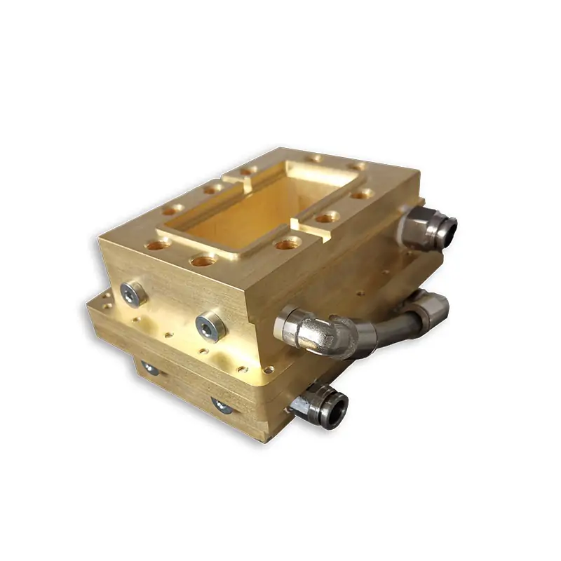
Pressure windows, inlets and seals
Choose by the job: a sealed RF boundary, a gas connection or a flange seal.
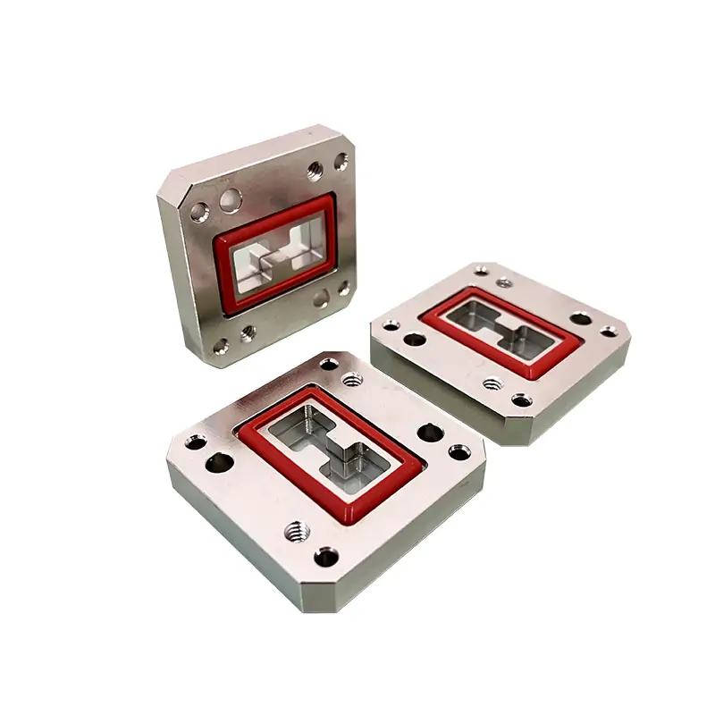
Pressure windows
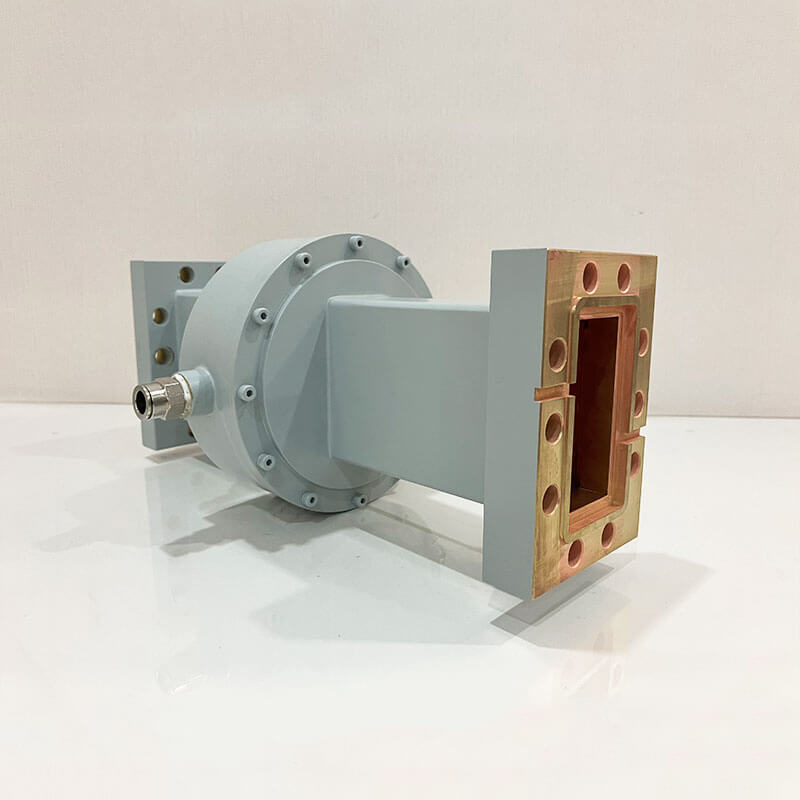
Select a pressure window when the RF path must pass through a sealed boundary. Rectangular WR and double-ridged WRD versions have separate model tables.
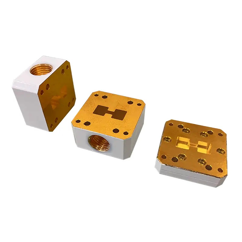
Pressure inlet sections
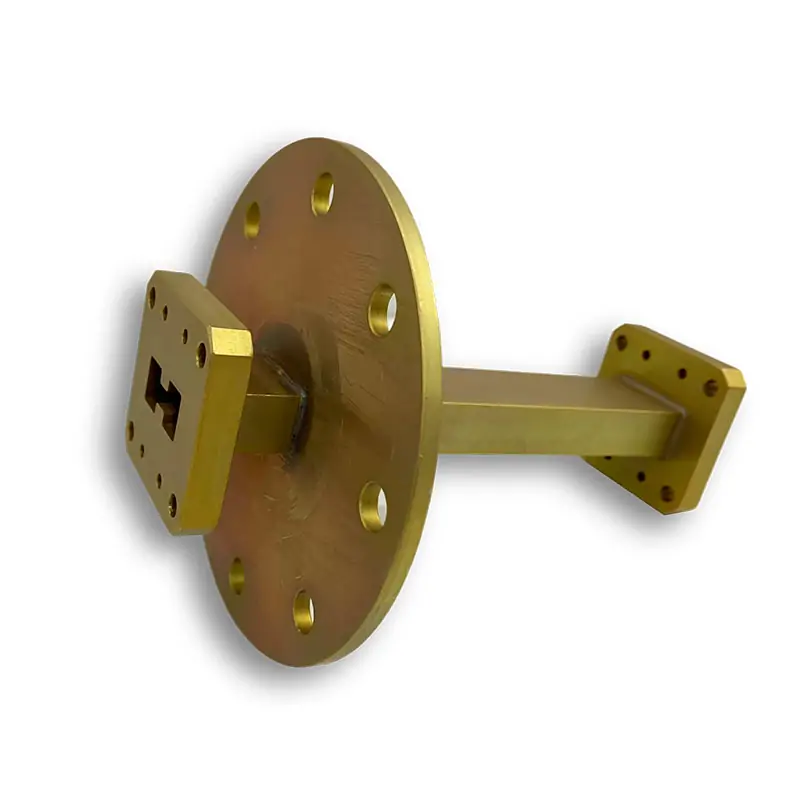
Select an inlet section for the gas port. Specify thread standard, valve or fitting, tube diameter, section length and access for the connection.

Gaskets and O-rings
Choose a non-conductive seal for pressure-only sealing, or a conductive gasket when the joint also needs an RF contact path. Match the groove and sealing face.
Pressure-window specifications
Compare these catalog examples, then open the full model table for your WR or WRD size. Pressure and power limits belong to the selected construction.
| Published model | Waveguide / GHz | VSWR max. | Pressure / average power | Cover / grooved flange |
|---|---|---|---|---|
| DH-32WAL… | WR2842.6–3.95 GHz | 1.15:1 | Up to 45 PSIGUp to 1000 W | UDR32 / PDR32 |
| DH-120WAL… | WR759.84–15 GHz | 1.15:1 | Up to 45 PSIGUp to 800 W | UBR120 / PBR120 |
| DH-650DRWPW… | WRD6506.5–18.0 GHz | 1.15:1 | Up to 45 PSIGUp to 800 W | FPWRD650D28 / FMWRD650D28 |
The three rows list Al/Cu bodies and Teflon/Fiberglass/Ceramics window options. Rectangular rows list Chromate finish; the WRD650 row lists Chromate/Painted. The ellipsis is part of the published model prefix; confirm the complete ordering code.
A single component rating does not establish the working pressure of the complete line. Include the mating flanges, seals, joints, gas equipment and the agreed leakage test in the review.
WR340 quartz window for 2.45 GHz

A 16 mm-thick window with cover and grooved flange faces. The specifications opposite apply to this build.
- Model
- DH-26WPW16
- Waveguide size
- WR340
- Frequency
- 2.45 GHz ± 25 MHz
- VSWR
- 1.5 Max
- Average power
- 10 KW
- Pressure
- 30 PSI Max
- Window material
- Quartz
- Flanges
- FDP26 (Cover) / FDM26 (Grooved)
- Body material
- Aluminum
- Finish
- Chromate
- Operating temperature
- -20℃–80℃
- Overall size
- 138 × 95 × 16 mm


VSWR and transmission test photos
Include the operating band, maximum VSWR, insertion-loss limit and pressure-test requirement with your drawing.
These photos document the published example. Ask for the inspection records required for your own order.
Gas inlet connections
Specify the thread, fitting and available installation length along with the waveguide size.
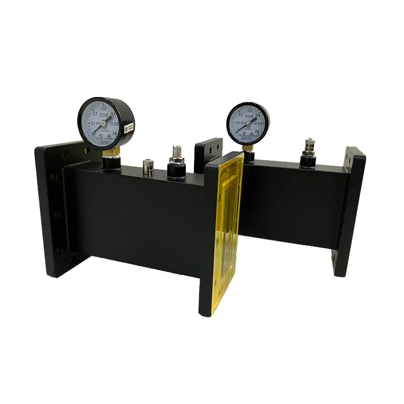
WR75 rectangular inlet
- Model prefix
- DH-120WPISV…
- Frequency
- 9.84–15 GHz
- Published row
- VSWR 1.05:1; pressure 45 PSIG
- Gas connection
- 1/8-27 NPTF; Schrader valves
- Lengths
- 19, 108, 152 mm
- Flanges
- UBR120 / PBR120
Double-ridged inlet connections
- Thread options
- G1/8, G1/4, G3/8, G1/2
- Connections
- Schrader valve, Pagoda connector or push-in fitting
- Tube O.D.
- 4, 6, 8, 10, 12, 16 mm
- Lengths
- 19, 108, 152 mm
- Flanges
- FPWRD cover or FMWRD grooved; model-specific suffixes
Thread check: Dolph’s web tables and PDFs use NPTF, NPT and G designations in different places. Include the mating fitting or thread drawing in your RFQ so the exact connection can be agreed.
For gas connection and pressure-control details, read the waveguide pressure inlet selection guide.
Flange gaskets and O-rings
Pressure-only sealing
For pressure-only sealing, match a non-conductive gasket or O-ring to the flange groove, cross-section and inside dimensions.
Pressure and RF sealing
For pressure sealing with an RF contact path, specify a conductive gasket and the mating flange faces. Include any leakage or electrical acceptance limits.
Flange and groove dimensions
The gasket table lists WR650–WR28 sizes with PAR, PBR and CPR/PDR references. Provide the groove dimensions and full or half-gasket arrangement.
For flange-face sealing, compare the die-cut waveguide gasket range. The gasket and O-ring selection guide explains the sealing choices.
Related waveguide components


PDF drawings and flange dimensions
Request a quote for your assembly
For a replacement, include the existing part number and a photo of each mating face. For a new assembly, send the interface drawing and the requirements below.
- RF and pressureFrequency, WR/WRD size, average and peak power, duty cycle, VSWR/loss limits, gas, pressure or vacuum, temperature and leakage criterion.
- Mechanical fitBoth flange designations, groove/seal dimensions, material, finish, length and envelope. For inlets: thread, fitting, tube O.D. and access direction.
- Order detailsQuantity, required date, drawing revision and inspection documents.