
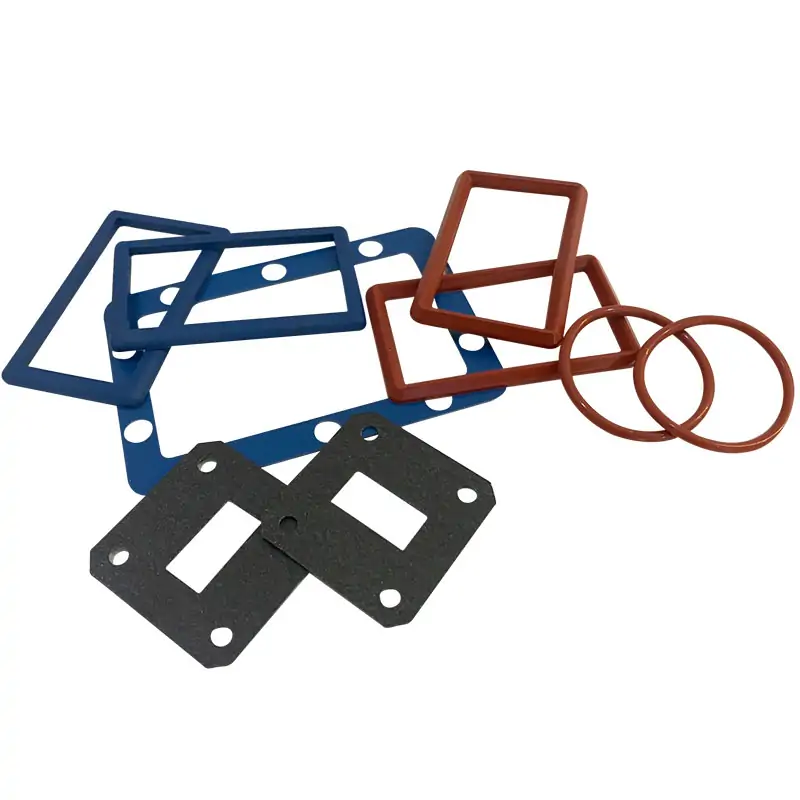
Waveguide sealing components
Waveguide Gasket and O‑Ring
Silicone gaskets and O‑rings for sealing waveguide flange joints. The published range includes conductive and non‑conductive options for PAR, PBR and CPR/PDR style interfaces, with listed models from WR650 down to WR28. Custom D‑type and O‑type dimensions can also be quoted against your flange drawing.
Start with the sealing job
Pressure seal only, or pressure and RF seal?
This is the first choice to make before matching a model. Then confirm the waveguide size, flange designation and the groove or sealing face that the gasket has to fit.
Pressure seal only
Non‑conductive gasket
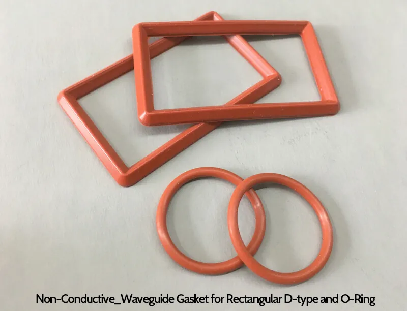
The published selection guidance calls for a non‑conductive gasket when the joint only needs a pressure seal. Silicone or neoprene O‑rings and rectangular seals are used to fit the matching flange groove.
Pressure + RF seal
Conductive gasket
For a joint that also needs an electrical contact path, the published guidance points to conductive gasket material. Conductive elastomers may use metallic filler; the required material should be confirmed with the quoted configuration.
Do not select by WR size alone. The same waveguide size can use different flange faces and sealing arrangements. Send the complete flange designation or a dimensioned drawing when it is available. No pressure rating, insertion loss or shielding value should be assumed from the gasket type alone unless it is stated on the approved drawing or test requirement.
Product details in pictures
See the seal styles before you match the flange.
The photos below show the main forms discussed in the product and selection guidance. They are useful for identification, but the final size still comes from the model data or approved drawing.
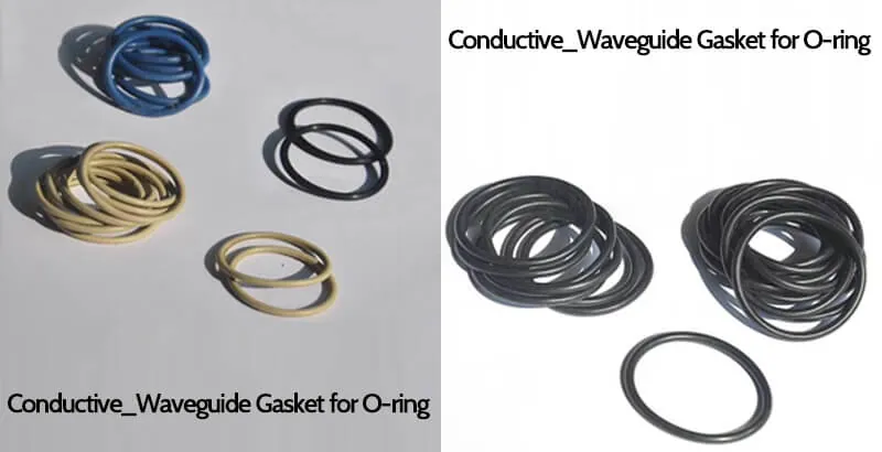
Conductive O‑rings
Shown in several sizes. Match the ring cross-section and inside diameter to the approved flange groove.
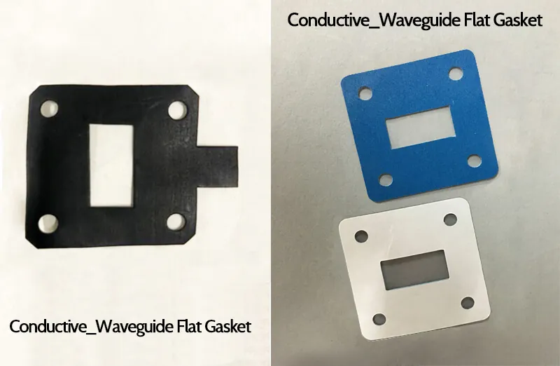
Flat gasket is a different style
For a flange-face gasket rather than a groove-fitting O‑ring or D‑type seal, review the separate die‑cut gasket product.
View Waveguide Gasket, Die CutPublished product overview
What is listed on the current product page
The summary below keeps the original specification fields. The model table further down retains every published row and dimensional entry.
- Flange Type
- MFO, MFD, MFOA (FBM/FBE, FDM, FAM/FAE)
- Waveguide Sizes
- WR650 to WR62 (custom sizes available)
- Material
- Conductive silicone rubber, Ordinary silicone rubber
- Flange Compatibility
- UG and CPR style flanges
- Customization
- Dimensions customizable per client requirements
Range note: the overview text says WR650 to WR62, while the published model table continues through WR51, WR42, WR34 and WR28. Use the model row and approved drawing when confirming the actual order.
The current page also mentions low insertion loss, reduced flange leakage, heat transfer and reduced outgassing as design objectives, but it does not publish numeric limits or test conditions for those statements. They are therefore not presented here as guaranteed performance values.
Drawing example
WR284 shows why the seal form matters.
The selection article includes separate WR284 examples for a rectangular D‑type gasket and an O‑ring. These are identification examples, not substitutes for the production drawing.
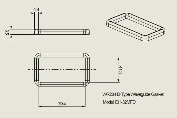
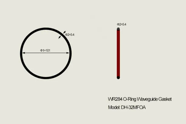
For the live order, match the drawing to the required flange style and the corresponding row in the model table below.
Complete published model data
Model, flange and gasket dimensions
All 17 product-page rows are retained here, including blank cells, flange designations, dimensions, electrical conductivity choices, material and document links. Scroll horizontally on smaller screens.
| Model | WG size | Gasket, full O-ring type for PAR style flanges | Gasket, full O-ring type for U/G, PBR style flanges | Gasket, full or half for CPR/PDR style flanges | Electrical conductivity | Material | Datasheet | |||
|---|---|---|---|---|---|---|---|---|---|---|
| PAR | I.D Φ1*Φ2(mm) | PBR SQ Cover Groove | I.D Φ1*Φ2(mm) | PDR CPRG | I.D A*B*T (mm) | |||||
| DH-14MFD… | WR650 | — | — | — | — | CPR650G | 174*92.2*8.5 | Conductive Non-conductive | Silicone | PDF · STEP |
| DH-18MFD… | WR510 | — | — | — | — | CPR510G | 136*72*5 | Conductive Non-conductive | Silicone | PDF · STEP |
| DH-22MFD… | WR430 | — | — | — | — | CPR430G | 117*63*5 | Conductive Non-conductive | Silicone | PDF · STEP |
| DH-26MFD… | WR340 | — | — | — | — | CPR340G | 94*51.5*5 | Conductive Non-conductive | Silicone | PDF · STEP |
| DH-32MFD… | WR284 | PAR32 | φ101*φ5.4 | — | — | CPR284G | 79.4*41.3*3.5 | Conductive Non-conductive | Silicone | PDF · STEP |
| DH-40MFD… | WR229 | PAR40 | φ82*φ5.4 | — | — | CPR229G | 63*34.5*3.5 | Conductive Non-conductive | Silicone | PDF · STEP |
| DH-48MFD… | WR187 | PAR48 | φ68.5*3.5 | — | — | CPR187G | 53.9*28.5*3.5 | Conductive Non-conductive | Silicone | PDF · STEP |
| DH-58MFD… | WR159 | PAR58 | φ60*3.5 | — | — | CPR159G | 46.7*26.5*4.9 | Conductive Non-conductive | Silicone | PDF · STEP |
| DH-70MFD… | WR137 | PAR70 | φ53*φ3.5 | — | — | CPR137G | 41.2*22.2*4.9 | Conductive Non-conductive | Silicone | PDF · STEP |
| DH-84MFO… | WR112 | — | — | PBR84 | φ40*φ2.6 | CPR112G | 34.9*19*4.9 | Conductive Non-conductive | Silicone | PDF · STEP |
| DH-100MFO… | WR90 | — | — | PBR100 | φ33*φ2.6 | CPR90G | 28.6*15.9*4.9 | Conductive Non-conductive | Silicone | PDF · STEP |
| DH-120MFO… | WR75 | — | — | PBR120 | φ28*φ2.6 | CPR75G | 23.77*14.25*2 | Conductive Non-conductive | Silicone | PDF · STEP |
| DH-140MFO… | WR62 | — | — | PBR140 | φ23.5*φ2.6 | CPR62G | 20.6*12.7*4.9 | Conductive Non-conductive | Silicone | PDF · STEP |
| DH-180MFO… | WR51 | — | — | PBR180 | φ20*φ2.4 | — | — | Conductive Non-conductive | Silicone | PDF · STEP |
| DH-220MFO… | WR42 | — | — | PBR220 | φ15.5*φ1.8 | — | — | Conductive Non-conductive | Silicone | PDF · STEP |
| DH-260MFO… | WR34 | — | — | PBR260 | φ14.0*φ1.8 | — | — | Conductive Non-conductive | Silicone | PDF · STEP |
| DH-320MFO… | WR28 | — | — | PBR320 | φ10.5*φ1.8 | — | — | Conductive Non-conductive | Silicone | PDF · STEP |
Dimensions and symbols are kept as printed on the current product page; “—” represents a blank source-table cell and should not be read as a confirmed incompatibility. The product-family PDF remains linked in every row. The web table and PDF can differ on individual dimensions, so the approved model drawing should control production dimensions.
Part-number guide
Read the published order code.
- 100Waveguide Size | WR90
- MFDGasket Style | For Rectangular Sealing Flanges
- MFOGasket Style | For Square Sealing Flanges
- CElectrical Conductivity | Conductive Materials
- NCElectrical Conductivity | Non-Conductive Materials
This example and the code meanings come from the original listing. Confirm the complete orderable suffix and final configuration on the quotation or drawing.
Applications listed by Dolph Microwave
Typical systems where these seals are used
The current product page names the following application areas. The gasket itself should still be selected from the actual flange interface and sealing requirement.
Telecommunications
Waveguide connections used in cellular and satellite communication systems.
Radar systems
Waveguide assemblies in air traffic control and maritime navigation radar systems.
Aerospace & defense
Waveguide sealing in communication and surveillance equipment.
Research & development
Laboratory and engineering setups where waveguide sections are repeatedly assembled or changed.
Industrial processing
Waveguide joints used in industrial microwave equipment and transmission runs.
Useful internal references
Check the flange and sealing method before you order.
These pages are useful when the existing part number is missing, the flange family is unclear, or you need a different gasket style.
Customers also review
Other parts around the same waveguide interface
These are separate products. They are included here because flange type, sealing style and the adjoining waveguide hardware are often checked together during an RFQ.

Waveguide Gasket, Die Cut
Flat flange-face gasket option to review when the joint does not use the same groove-fitting D‑type or O‑ring geometry.
View product →
Waveguide Flange Standard EIA & IEC
Use the flange reference to identify the mating face, hole pattern and standard designation before releasing a gasket size.
View product →
Seamless Flexible WG
Consider a flexible section when routing, vibration or installation alignment makes a fully rigid waveguide connection unsuitable.
View product →Technical documents
Use the PDF for reference, then confirm the exact model on the drawing.
The original product page provides the gasket specification sheet, flat gasket sheet and flange designation reference. These links are kept here so the technical files stay easy to reach.
Dolph Microwave’s published warranty states one year from the date of delivery against defective material and workmanship, subject to the company’s warranty terms. For final supply, the quotation and approved drawing should define the exact configuration and acceptance scope.




