
Broadband WRD Coverage
Standard families span WRD840 through WRD180, covering published operating ranges from 0.84 GHz to 40 GHz.
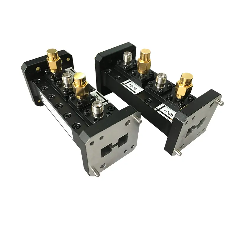
Dolph Microwave’s Double-Ridge Waveguide Loop Couplers deliver precision performance across 0.84–40 GHz, optimized for high-power RF systems like radar, 5G, and satellite communications. Engineered with WRD-series waveguides, these couplers feature 20–60 dB coupling (±1.5 dB accuracy), 1.15:1 VSWR, and 12–15 dB directivity. Available with N-Type, SMA, or 2.92mm connectors and corrosion-resistant aluminum/copper construction, they ensure reliability in demanding environments. Customizable flange types (flat/grooved) and Surtec-treated finishes meet MIL-STD standards.
Dolph Microwave’s Double-Ridge Waveguide Loop Couplers are precision-engineered components designed for high-power RF and microwave systems, operating across full waveguide frequency bands from 0.84 GHz to 40 GHz. Utilizing a robust double-ridge waveguide architecture, these couplers provide low-reflection performance with VSWR ≤1.15:1 and precise coupling values ranging from 20 dB to 60 dB, with consistent directivity of 12–15 dB. Ideal for applications demanding high power handling and wideband performance, they are available in WRD-series waveguide sizes, including WRD840 for 0.84–2.0 GHz and WRD180 for 18–40 GHz, and support coaxial interfaces such as N-Type, SMA, or 2.92 mm connectors.
Designed for broadband signal sampling in high-power RF systems, the range combines selectable coupling, directional monitoring and durable WRD interfaces.
Standard families span WRD840 through WRD180, covering published operating ranges from 0.84 GHz to 40 GHz.
Single-directional and dual-directional formats support forward-power, reflected-power or two-direction monitoring.
Published coupling values range from 20 dB to 60 dB, with N-Type, SMA or 2.92 mm female outputs selected according to the model range.
Aluminum or copper construction is available with cover and grooved flange combinations, Surtec corrosion protection and chromate or painted finishes.
A loop coupler samples a controlled portion of the electromagnetic energy traveling through the main double-ridge waveguide path. The sampled signal is routed to a coaxial output without requiring the primary high-power signal to be connected directly to lower-power measurement equipment.
The coupling port can provide a reduced-level representation of transmitted power for system supervision, calibration, control loops or protection circuits.
A directional or dual-directional arrangement can be configured to sample reflected energy and support load-condition or mismatch monitoring.
Match the coupler to the complete operating frequency range and the existing double-ridge waveguide size.
Choose the coupling value according to main-line power, instrument input range and required measurement margin.
Specify forward, reverse or dual-direction sampling, along with coupling connector, flange arrangement and orientation.
Double-ridge loop couplers provide reduced-level signal access for monitoring, measurement and protection functions in broadband RF and microwave systems.
Dolph Microwave can review custom coupling values, flange designs, connector arrangements, materials and finishes against the required operating band and system interface.
Specify coupling level, tolerance, forward or reverse sampling direction, single or dual outputs and required directivity.
Choose the WRD size, cover and grooved flange combination, connector orientation and available mounting clearance. Pressure-sealed construction can be evaluated when supported by project requirements and engineering review.
Define aluminum or copper construction, Surtec or chromate treatment, paint color, environmental exposure and flange-face requirements.
The table retains the original published model range, waveguide interfaces, coupling outputs, materials and finish information.
| Model | Freq. Range (GHz) |
WG Size | VSWR | Coupling (dB) |
Directivity (dB) |
Coupling Output | Flange Type | Material | Finish | Datasheet | ||
|---|---|---|---|---|---|---|---|---|---|---|---|---|
| Cover | Grooved | DWG | STEP | |||||||||
| DH-840DRWHC30… | 0.84–2.0 | WRD840 | 1.15:1 | 20–60 | 12–15 | N-K | FPWRD840U24 | FMWRD840U24 | Al/Cu | Chromate/Painted | DWG | STEP |
| DH-150DRWHC30… | 1.5–3.6 | WRD150 | 1.15:1 | 20–60 | 12–15 | N-K | FPWRD150D24 | FMWRD150D24 | Al/Cu | Chromate/Painted | DWG | STEP |
| DH-200DRWHC30… | 2.0–4.8 | WRD200 | 1.15:1 | 20–60 | 12–15 | N-K | FPWRD200D24 | FMWRD200D24 | Al/Cu | Chromate/Painted | DWG | STEP |
| DH-250DRWHC30… | 2.6–7.8 | WRD250 | 1.15:1 | 20–60 | 12–15 | N-K | FPWRD250D30 | FMWRD250D30 | Al/Cu | Chromate/Painted | DWG | STEP |
| DH-350DRWHC30… | 3.5–8.2 | WRD350 | 1.15:1 | 20–60 | 12–15 | N-K | FPWRD350D24 | FMWRD350D24 | Al/Cu | Chromate/Painted | DWG | STEP |
| DH-475DRWHC30… | 4.75–11.0 | WRD475 | 1.15:1 | 20–60 | 12–15 | N-K | FPWRD475D24 | FMWRD475D24 | Al/Cu | Chromate/Painted | DWG | STEP |
| DH-500DRWHC30… | 5.0–18.0 | WRD500 | 1.15:1 | 20–60 | 12–15 | N-K | FPWRD500D36 | FMWRD500D36 | Al/Cu | Chromate/Painted | DWG | STEP |
| DH-580DRWHC30… | 5.8–16.0 | WRD580 | 1.15:1 | 20–60 | 12–15 | N-K | FPWRD580D28 | FMWRD580D28 | Al/Cu | Chromate/Painted | DWG | STEP |
| DH-650DRWHC30… | 6.5–18.0 | WRD650 | 1.15:1 | 20–60 | 12–15 | SMA-K | FPWRD650D28 | FMWRD650D28 | Al/Cu | Chromate/Painted | DWG | STEP |
| DH-700DRWHC30… | 7.0–18.5 | WRD700 | 1.15:1 | 20–60 | 12–15 | SMA-K | FPWRD700D26 | FMWRD700D26 | Al/Cu | Chromate/Painted | DWG | STEP |
| DH-750DRWHC30… | 7.5–18.0 | WRD750 | 1.15:1 | 20–60 | 12–15 | SMA-K | FPWRD750D24 | FMWRD750D24 | Al/Cu | Chromate/Painted | DWG | STEP |
| DH-110DRWHC30… | 11.0–26.5 | WRD110 | 1.15:1 | 20–60 | 12–15 | 2.92-K | FPWRD110C24 | FMWRD110C24 | Al/Cu | Chromate/Painted | DWG | STEP |
| DH-180DRWHC30… | 18.0–40.0 | WRD180 | 1.15:1 | 20–60 | 12–15 | 2.92-K | FPWRD180C24 | FMWRD180C24 | Al/Cu | Chromate/Painted | DWG | STEP |
The example below shows how waveguide size, directionality, coupling, connector, flange and material are encoded. Confirm the final code in the approved quotation.
DH-840DRWHC30NKPMAAll Dolph-MW models include a Surtec/corrosion-protection treatment and are painted flat black. Flanges are unplated, polished and Surtec treated. Other finishes and paint colors are available upon request.
Complete inputs are required to verify the coupling port, waveguide interfaces, sampling direction and performance across the intended operating band.
Request Technical ReviewUse the available technical files for related product and flange-reference information.
Dolph Microwave warrants our products to be free from defective material and workmanship for a period of one year from the date of delivery. All defective parts will be replaced and repair work required by normal use will be performed, without charge, within this one year period. This warranty shall be exclusive and in lieu of all other warranties expressed or implied.



FengHuiNan Road NO.34, High-Tech Zone, Xi an, China
Tel/Fax: (+86) 29-8881-0979
E-mail: Sales@dolphmicrowave.com







