Waveguides provide low-loss and high-power signal transmission for microwave and millimeter-wave systems. A waveguide frequency bands chart helps engineers compare WR sizes, operating frequency ranges, cutoff frequencies, flange interfaces, and application suitability before selecting components for radar systems, satellite communications, test equipment, antenna feeds, and custom RF assemblies.
Correct selection should not rely on frequency range alone. The final choice should also consider insertion loss, VSWR, power handling, phase stability, mechanical tolerance, flange compatibility, material, plating, pressurization requirement, and system-level installation conditions. Dolph Microwave supplies precision waveguide components, waveguide assemblies, waveguide-to-coax adapters, horn antennas, and SATCOM antenna-related solutions for projects where these parameters must be reviewed together.
Table of Contents
WR Sizes
WR Designation Meaning
The WR prefix stands for rectangular waveguide. The number after WR indicates the approximate broad-wall inner dimension in hundredths of an inch. For example, WR-90 has a broad-wall inner width of approximately 0.900 inch, or 22.86 mm. The broad-wall dimension is usually marked as a, and the narrow-wall dimension is usually marked as b. These two internal dimensions determine the waveguide cutoff frequency, usable frequency band, bandwidth, power handling capability, and dominant propagation mode.
This naming rule is important because a WR number is not just a model code. It is directly connected to the physical size of the rectangular waveguide. When the frequency increases, the required waveguide size becomes smaller. This is why X-band waveguides such as WR-90 are physically larger than Ka-band waveguides such as WR-28.
Engineers should also distinguish between WR size and flange model. A WR designation defines the waveguide opening size. A flange designation defines the mechanical connection interface. These two items are related, but they are not the same thing. A correct waveguide assembly normally requires both the proper WR size and the proper mating flange standard.
Common WR Size Chart
The following chart lists several common rectangular waveguide sizes used in microwave, SATCOM, radar, and RF test applications. The operating bands shown are typical recommended ranges, not the complete theoretical single-mode range. Final design should always verify the supplier drawing, test data, system frequency, power level, flange interface, and installation condition.
| WR Designation | Broad Wall a | Narrow Wall b | Typical Operating Band | TE10 Cutoff Frequency | Common Band Reference |
|---|---|---|---|---|---|
| WR-90 | 22.86 mm / 0.900 in | 10.16 mm / 0.400 in | 8.2–12.4 GHz | 6.56 GHz | X-band |
| WR-75 | 19.05 mm / 0.750 in | 9.525 mm / 0.375 in | 10.0–15.0 GHz | 7.87 GHz | X / Ku-band |
| WR-62 | 15.80 mm / 0.622 in | 7.90 mm / 0.311 in | 12.4–18.0 GHz | 9.49 GHz | Ku-band |
| WR-51 | 12.95 mm / 0.510 in | 6.48 mm / 0.255 in | 15.0–22.0 GHz | 11.58 GHz | Ku / K-band |
| WR-42 | 10.67 mm / 0.420 in | 4.32 mm / 0.170 in | 18.0–26.5 GHz | 14.05 GHz | K-band |
| WR-34 | 8.64 mm / 0.340 in | 4.32 mm / 0.170 in | 22.0–33.0 GHz | 17.36 GHz | Ka-band |
| WR-28 | 7.11 mm / 0.280 in | 3.56 mm / 0.140 in | 26.5–40.0 GHz | 21.08 GHz | Ka-band |
| WR-22 | 5.69 mm / 0.224 in | 2.84 mm / 0.112 in | 33.0–50.0 GHz | 26.35 GHz | Q / V-band |
For procurement, the WR size table should be used as an initial reference only. Two components with the same WR size may still differ in flange type, length tolerance, surface finish, plating, material, pressure sealing, power rating, and test requirements. For custom waveguide parts, drawings and RF specifications should be confirmed before production.
Waveguide Flange Matching
Waveguide flanges define the mechanical interface between waveguide components. They affect alignment, repeatability, leakage control, pressurization, gasket use, and assembly reliability. A waveguide may have the correct WR size but still fail to mate with another component if the flange standard, bolt pattern, gasket groove, or alignment method is different.
Common flange references include UG-style military flanges, commercial rectangular flanges such as CPR, CPRG, and CPRF, and IEC/R-series flange designations such as UBR, PBR, UDR, and PDR. These naming systems should not be guessed from the numbers alone. A flange model must be checked against the waveguide size, interface drawing, mating component, gasket requirement, and pressure sealing condition.
| Flange Check Item | Why It Matters | Selection Risk If Ignored |
|---|---|---|
| WR size | Confirms the waveguide opening matches the component | Mechanical mismatch or severe RF discontinuity |
| Flange standard | Defines bolt pattern, face type, and interface geometry | Parts may not assemble correctly |
| Gasket groove | Required for sealing or pressurized waveguide systems | Leakage or pressure failure |
| Alignment pins | Improve repeatability in precision test and high-frequency systems | Higher VSWR or phase variation |
| Surface flatness | Affects contact quality between mating flanges | RF leakage and unstable connection |
For high-frequency bands such as Ka-band, Q-band, V-band, and above, flange precision becomes more critical because small mechanical errors can create measurable RF performance degradation. For this reason, flange selection should be handled as part of the RF design, not as a simple hardware accessory decision.
Frequency Ranges
Operating Band Range
A rectangular waveguide operates effectively only within a defined frequency range. The signal frequency must be above the dominant TE10 cutoff frequency and below the range where higher-order modes become a practical problem. The published operating band normally includes an engineering safety margin, which helps control insertion loss, VSWR, dispersion, and mode stability.
For example, WR-90 has a TE10 cutoff frequency of approximately 6.56 GHz, but its common operating band is 8.2–12.4 GHz. The lower edge is set above cutoff to avoid poor propagation behavior. The upper edge stays below the higher-order mode region to maintain stable single-mode operation. This is why the practical operating band is narrower than the theoretical limit.
In real systems, the usable band may also be limited by the connected components. A waveguide straight section may support the frequency, but the complete assembly may include bends, twists, adapters, couplers, windows, transitions, gaskets, or antennas. Each item can affect bandwidth, return loss, power handling, and phase performance.
Cutoff Frequency
The dominant TE10 cutoff frequency is mainly determined by the broad-wall inner dimension of the rectangular waveguide. A simplified formula is:
fc = c / 2a
In this formula, fc is the cutoff frequency, c is the speed of light, and a is the broad-wall inner dimension of the waveguide. For quick engineering estimation when a is in millimeters, the formula can be approximated as:
fc(GHz) ≈ 150 / a(mm)
| WR Size | Broad Wall a | Estimated TE10 Cutoff | Typical Operating Band |
|---|---|---|---|
| WR-90 | 22.86 mm | 6.56 GHz | 8.2–12.4 GHz |
| WR-62 | 15.80 mm | 9.49 GHz | 12.4–18.0 GHz |
| WR-42 | 10.67 mm | 14.05 GHz | 18.0–26.5 GHz |
| WR-28 | 7.11 mm | 21.08 GHz | 26.5–40.0 GHz |
Below the cutoff frequency, the waveguide cannot support normal propagation in the dominant mode. Near cutoff, attenuation increases and performance becomes unstable. For this reason, engineers should not select a waveguide simply because the frequency is slightly above the theoretical cutoff. The recommended operating band provides a safer basis for RF design.
Band Overlap
Adjacent WR sizes often have overlapping operating ranges. This overlap gives engineers flexibility when balancing size, power handling, insertion loss, manufacturing tolerance, and interface requirements. For example, WR-90 and WR-75 both cover part of the X/Ku transition region. WR-75 and WR-62 also overlap around the lower Ku-band region.
Band overlap does not mean the two waveguide sizes are interchangeable in every system. A larger waveguide may offer better power handling but may also be physically heavier and harder to integrate. A smaller waveguide may fit compact assemblies better, but it may have higher loss or lower power capacity. The final choice should be made according to the complete system requirement.
| Selection Factor | Larger WR Size May Help With | Smaller WR Size May Help With |
|---|---|---|
| Power handling | Higher power margin | Lower size and weight |
| Mechanical integration | More robust interface | Compact assembly design |
| Insertion loss | Potentially lower loss in some bands | Shorter and lighter transmission paths |
| Frequency planning | Better margin near lower frequencies | Better fit for higher-frequency systems |
| Component availability | May match legacy systems | May match modern compact modules |
For wideband systems, transition design is also important. Waveguide transitions, adapters, and waveguide-to-coax interfaces should be selected carefully to avoid unnecessary mismatch, added insertion loss, or poor repeatability at the reference plane.
Applications
Radar Systems
Radar systems use waveguides because they can handle high power with low transmission loss. X-band, Ku-band, and Ka-band waveguides are widely used in defense radar, weather radar, airborne radar, marine radar, phased-array radar, and tracking systems. In these applications, phase stability, power capacity, insertion loss, and mechanical precision are critical.
For radar applications, waveguide selection should consider both peak power and average power. Pulsed radar systems may have high peak power even when the average power is moderate. If the waveguide size, surface finish, flange contact, or pressurization design is not suitable, the system may face arcing, breakdown, leakage, or unstable RF performance.
- Use suitable WR size for the radar operating band.
- Check peak power and average power requirements separately.
- Review flange contact quality and pressure sealing when needed.
- Control phase consistency in phased-array and tracking applications.
- Use precision bends, twists, couplers, and transitions where layout constraints exist.
Satellite Communications
Satellite communication systems rely on waveguides for signal transmission between antennas, feeds, filters, transceivers, OMTs, couplers, and other RF modules. C-band, X-band, Ku-band, Ka-band, and V-band applications may all require waveguide components depending on the earth station, gateway, payload, terminal, or test system design.
In SATCOM systems, engineers should not only confirm the frequency band. They should also check insertion loss, VSWR, polarization requirement, flange type, environmental sealing, corrosion resistance, and antenna feed compatibility. For outdoor earth station and gateway applications, weather exposure and long-term mechanical stability also matter.
| SATCOM Area | Waveguide Requirement | Typical Component Direction |
|---|---|---|
| Earth station antenna | Low-loss feed connection | Waveguide assemblies, bends, twists, adapters |
| Gateway system | Stable high-frequency transmission | Precision waveguide runs and transitions |
| Antenna feed system | Polarization and interface matching | OMT, feed components, custom waveguide parts |
| Ka-band terminal | Compact and accurate RF path | WR-28 components and precision flanges |
| Test setup | Repeatable measurement interface | Calibration kits, adapters, waveguide sections |
Dolph Microwave supports SATCOM and antenna-related projects with waveguide components, waveguide horn antennas, standard gain horn antennas, antenna feed parts, and custom assemblies for project-specific interface requirements.
Test and Measurement
Waveguides are widely used in RF and microwave test systems, including vector network analyzer setups, calibration kits, spectrum analyzer paths, antenna measurement systems, material testing fixtures, and millimeter-wave laboratories. In these environments, repeatability and mechanical precision are often just as important as frequency coverage.
A test setup should use waveguide components with stable flange alignment, controlled insertion loss, low VSWR, and suitable surface finish. Temporary or low-precision components may be acceptable in non-critical positions, but they should not be used at formal measurement reference planes where repeatability is required.
- Confirm the operating band of the VNA extender or test module.
- Select the matching WR size and flange interface.
- Use precision waveguide sections for reference-plane connections.
- Check adapter loss before using waveguide-to-coax transitions.
- Protect flange faces from scratches, dents, and contamination.
- Use calibration kits and standards suitable for the test frequency band.
Selection Pitfalls
Many waveguide selection errors come from treating one parameter as the only decision factor. A frequency band chart is useful, but it does not replace a complete RF and mechanical review. The most common mistakes include selecting by frequency alone, matching flanges by name without checking drawings, ignoring cutoff margin, and overlooking power handling requirements.
| Common Mistake | Why It Happens | Better Practice |
|---|---|---|
| Selecting only by operating frequency | The target frequency appears inside the published band | Also review power, loss, VSWR, phase, and mechanical interface |
| Ignoring cutoff margin | The frequency is above theoretical cutoff | Use the recommended operating band, not the bare cutoff limit |
| Matching flanges by model number alone | Flange codes are confused with WR size codes | Check the flange drawing, bolt pattern, gasket groove, and mating standard |
| Overlooking peak power | Only average power is reviewed | Check peak power, average power, pressurization, and breakdown margin |
| Using generic adapters in precision systems | The adapter fits mechanically | Confirm insertion loss, return loss, repeatability, and calibration impact |
Waveguide selection is a system-level decision. A correct solution should balance frequency coverage, mode stability, power handling, loss, phase accuracy, flange matching, manufacturing tolerance, environmental conditions, and cost. When the project involves custom mechanical interfaces, high-frequency operation, or strict RF performance, early specification review can prevent costly redesign.
Need Waveguide Components for Your Frequency Band?
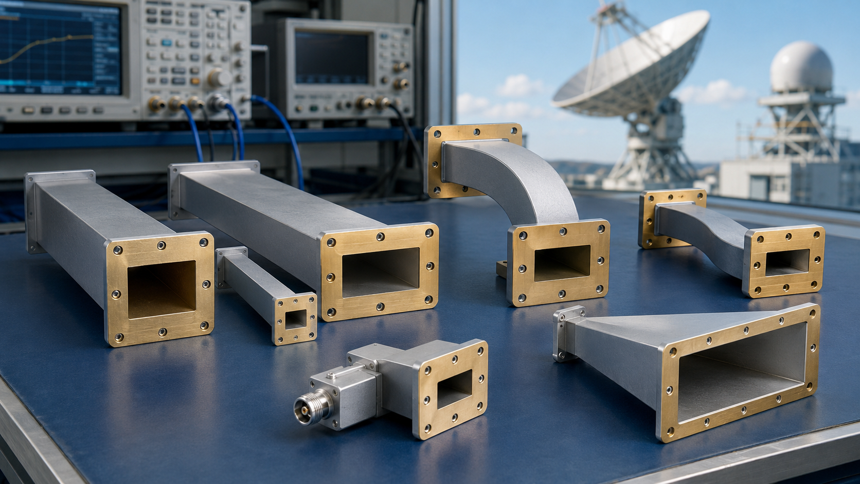
Dolph Microwave designs and manufactures waveguide components for microwave, millimeter-wave, satellite communication, aerospace, defense, radar, and RF test applications. Available solutions include waveguide tubes, waveguide bends, waveguide twists, waveguide transitions, waveguide-to-coax adapters, couplers, power dividers/combiners, horn antennas, standard gain horn antennas, and custom waveguide assemblies.
If your project requires a specific WR size, flange type, frequency range, power level, material, plating, or mechanical interface, Dolph Microwave can support specification review and custom manufacturing based on your application requirements.


