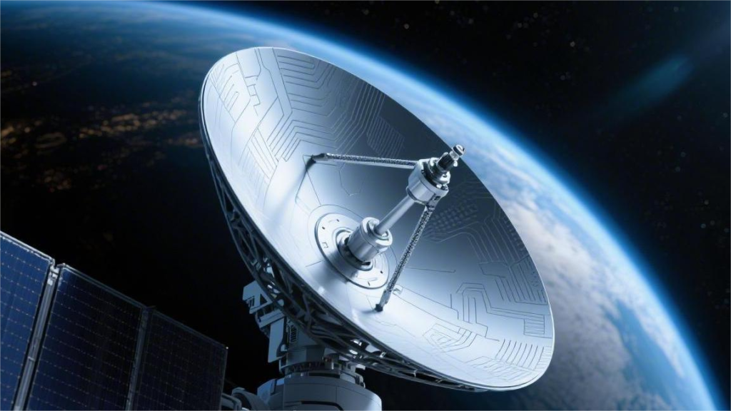
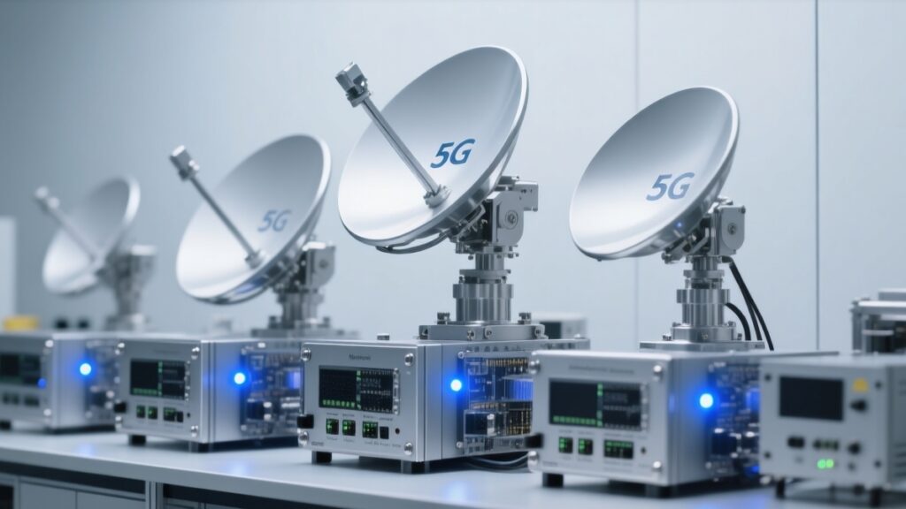
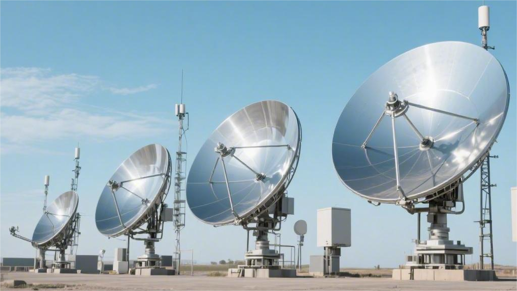
+86 29 8881 0979

default

How to Measure Waveguide Flange Sizes Accurately

To accurately measure waveguide flange sizes, use ​​precision calipers​​ (resolution 0.01mm) to verify ​​flange outer diameter​​ (WR-90 standard: 58.17±0.05mm) and ​​bolt circle diameter​​ (47.55±0.03mm for UG-39/U). Check ​​flatness​​ with optical flats (<0.02mm deviation across surface) and measure ​​groove depth​​ (3.18±0.05mm for choke flanges) with depth micrometers. For ​​alignment​​, use go/no-go gauges to test pin-slot tolerance […]

How to Measure Waveguide Flange Sizes Accurately Read More »

How to Test Waveguide Connector Performance

To test waveguide connector performance, measure ​​insertion loss​​ (should be <0.1 dB for Ka-band) and ​​VSWR​​ (target <1.25:1) using a vector network analyzer. Conduct ​​durability tests​​ (500+ mating cycles) while monitoring ​​contact resistance​​ (must stay below 5mΩ). Verify ​​EMI shielding​​ effectiveness (>90dB attenuation at 40GHz) and ​​thermal stability​​ (-55°C to +125°C operating range). For millimeter-wave

How to Test Waveguide Connector Performance Read More »

What Are the Main Waveguide Flange Types

Waveguide flanges are critical for connecting RF/microwave systems, with four primary types dominating 90% of industrial use: ​​UPC flanges​​ (WR-90 standard, 8.2–12.4 GHz, 0.1dB insertion loss) are universal for lab equipment; ​​CPR flanges​​ feature choke grooves for military radars, achieving -80dB leakage; ​​cover flanges​​ enable quick testing with precision 2µm surface finishes; and ​​square flanges​​

What Are the Main Waveguide Flange Types Read More »

What Is a Waveguide Dummy Load Used For

A waveguide dummy load absorbs RF/microwave energy (e.g., 1–40 GHz) to test transmitters safely, preventing signal reflection. Typical models handle 50W–50kW power with VSWR <1.1. Used in radar calibration (e.g., 90% of military systems) and 5G base station testing, featuring water-cooled designs for sustained 30-minute 100% duty cycles. Load Functionality That night, Tom, the on-duty

What Is a Waveguide Dummy Load Used For Read More »

What Materials Make Ideal Waveguide Gaskets

Silver-plated EPDM (0.03–0.1mm thickness) dominates for 18–110 GHz systems, offering <0.05 dB insertion loss and 80°C thermal stability. Conductive fluoroelastomers (MIL-G-83528B) handle 40+ dB shielding in military radars. Install with 7–12 N·m torque on WR-90 flanges; replace every 5,000 operational hours in high-vibration environments. Material Requirements Last year, during the vacuum thermal cycling test of

What Materials Make Ideal Waveguide Gaskets Read More »

When to Use Waveguide Flange Covers

Use waveguide flange covers during transport/storage (preventing 0.1–5 dB insertion loss from dust) or inactive system periods. Essential in corrosive environments (e.g., coastal 5G sites), they block moisture ingress per MIL-STD-348A. Install with torque-controlled bolts (12–15 N·m for WR-90) and replace every 6–12 months in high-humidity areas. Protection Requirements Last June, the AsiaStar 9 satellite

When to Use Waveguide Flange Covers Read More »

Why Are Waveguide Flange Specifications Critical

Waveguide flange specifications ensure ​​<0.1dB insertion loss​​ by maintaining ​​sub-0.05mm alignment tolerances​​ (per MIL-STD-392). Standardized flanges (e.g., ​​WR-90 UG-387/U​​) prevent RF leakage with ​​>60dB shielding​​, while ​​gold-plated contacts​​ and ​​torque limits (8-12 in-lb)​​ guarantee ​​VSWR <1.15​​ up to ​​40GHz​​ in radar/satellite systems. Standard Importance At three in the morning, alarms blared at the Houston Satellite

Why Are Waveguide Flange Specifications Critical Read More »

Why Choose Waveguide Power Splitters over Coaxial

Waveguide power splitters outperform coaxial in high-frequency applications (18-110 GHz) with ​​<0.2dB insertion loss​​ (vs. coaxial’s ​​0.5-1dB​​) and ​​>30dB isolation​​. Their ​​aluminum/millimeter-precise​​ construction minimizes signal degradation, handling ​​kW-level power​​ without overheating, while ​​flange-mounted​​ designs ensure ​​<0.05mm alignment errors​​ for consistent ​​phase matching​​ in radar/5G systems. Performance Comparison Last year, engineers at Intelsat discovered a critical

Why Choose Waveguide Power Splitters over Coaxial Read More »

Why Are Waveguide Circulators Essential for 5G

Waveguide circulators are critical for 5G mmWave systems (24-40 GHz) due to their high isolation (>20 dB) and low insertion loss (<0.5 dB), enabling full-duplex operation in massive MIMO antennas. Their ferrite-based non-reciprocal design prevents signal interference between Tx/Rx paths while handling high power (up to 100W), with temperature-stable performance (-40°C to +85°C) ensuring reliable

Why Are Waveguide Circulators Essential for 5G Read More »

How Do Waveguide Adapters Prevent Signal Loss

Waveguide adapters minimize signal loss (typically <0.1 dB) by precisely matching impedance between different waveguide sizes/connectors through tapered transitions (e.g., 10-15° flare angles) and ultra-smooth interior surfaces (Ra <0.4 μm). Their quarter-wavelength choke joints and gold-plated brass/aluminum construction maintain VSWR <1.2 up to 40 GHz, while alignment pins ensure sub-50μm positional accuracy to prevent mode

How Do Waveguide Adapters Prevent Signal Loss Read More »

Scroll to Top
Blank Form (#3)