Design of Conductive Elastomer Waveguide Gaskets | Function, Material, Manufacturing Process
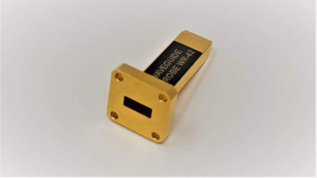
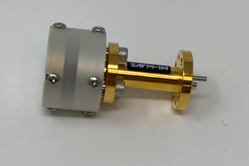
Function: Achieve waveguide sealing and electromagnetic shielding (X-band 8-12GHz, shielding effectiveness ≥60dB). Material: Silicone rubber matrix + 3-5wt% carbon nanotubes (CNT), tensile strength ≥5MPa. Process: Internal mixer blending at 150°C for 30min → Compression molding (10MPa/15min) → Plasma cleaning surface. Final product is highly elastic with stable conductivity. Function Achieves 105dB shielding effectiveness at 40GHz […]