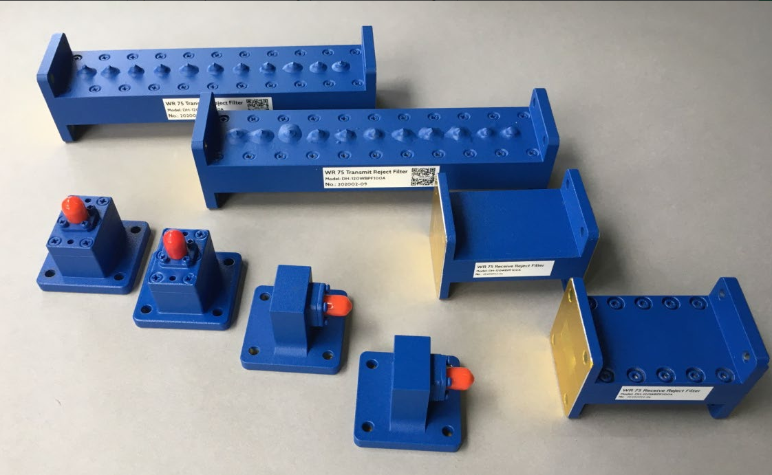
Microwave Bends
Microwave bends are crucial components in guiding microwave signals through complex circuit layouts, ensuring signal integrity and efficient routing in various applications. These bends accommodate the need for directional changes in transmission lines, supporting seamless signal flow in telecommunications, radar systems, and other microwave technology-based applications. Their design optimizes performance while minimizing signal loss and reflection.
Discover the cutting-edge technology of Microwave Bends, a transformative solution in microwave transmission designed to enhance signal routing with precision and efficiency. Our Microwave Bends stand out for their quick delivery, versatile configuration options, and superior power handling capabilities. Catering to both standard and customized needs, these bends introduce a new level of performance in microwave system design.
Exceptional Features
- Versatile Configuration: Offers both E and H bends in sweep or miter types to fit specific application requirements.
- Broad Frequency Range: Supports frequencies of 915 MHz and 2450 MHz, accommodating a wide spectrum of microwave applications.
- High Power Handling: Capable of managing power levels from 6 KW to 20 KW cw, ensuring reliability under high power conditions.
- Customizable Bend Degrees: Available in 45°, 60°, and 90° bends, providing flexibility in system layout and design.
- Material Excellence: Constructed from premium materials like Aluminum (Al) and Copper (Cu), enhancing durability and performance.
- Quick Delivery: Ensures fast turnaround times, meeting project deadlines with efficiency.
- Tailored Solutions: Both standard and customized mechanical configurations are available, offering bespoke solutions for unique system requirements.
Applications
Microwave Bends find their applications in a myriad of fields, demonstrating versatility and efficiency:
- Telecommunications: Enhances signal routing in complex network infrastructures, improving communication reliability.
- Radar Systems: Facilitates precise signal direction changes, crucial for accurate radar operation and data collection.
- Satellite Communications: Ensures optimal signal flow in satellite uplink and downlink paths, enhancing global connectivity.
- Research Laboratories: Supports experimental setups requiring precise microwave signal manipulation.
- Medical Equipment: Plays a vital role in medical devices where microwave energy is used for diagnostic or therapeutic purposes.
Technical Specifications
For a clearer understanding, here’s a brief overview of the technical specifications:
| Specification | Details |
|---|---|
| Frequency Range | 915 MHz and 2450 MHz |
| Handling Power | 6 KW, 10 KW, up to 20 KW cw |
| Model Types | E and H, sweep or miter |
| Bend Degrees | 45°, 60°, 90° |
| Material | Aluminum (Al), Copper (Cu) |
This table underscores the flexibility and performance capabilities of Microwave Bends, highlighting their adaptability to various system requirements.
Experience the Future of Microwave Transmission
Microwave Bends redefine the landscape of microwave signal transmission, offering unparalleled flexibility, efficiency, and performance. With a focus on innovation, we ensure that our solutions meet the evolving needs of industries reliant on microwave technology. Embrace the next level of system design and performance with our cutting-edge Microwave Bends, where precision meets reliability.