Waveguides operate in TE (Transverse Electric), TM (Transverse Magnetic), and TEM (Transverse Electromagnetic) modes. TE and TM dominate microwave frequencies (1-300 GHz), with TE10 being most common in rectangular waveguides (cutoff frequency ~6.56 GHz for WR-90).
TEM mode, used in coaxial cables, supports DC to 100+ GHz but lacks waveguide applications. Mode selection depends on frequency, power handling (e.g., TE10 handles 1kW+ at 10GHz), and signal purity requirements.
Table of Contents
Basic Waveguide Types
Waveguides are essential for directing electromagnetic waves with minimal loss, commonly used in radar, satellite communications, and microwave systems. The most widely used types are rectangular, circular, and ridged waveguides, each optimized for different frequency ranges and power levels. Rectangular waveguides dominate 80% of commercial applications due to their simple design and efficient 8-40 GHz operation. Circular waveguides handle higher power (up to 10 kW) and support rotating joints, while ridged waveguides offer 30% wider bandwidth but at a 15% higher cost.
| Type | Frequency Range (GHz) | Power Handling (kW) | Attenuation (dB/m) | Common Applications |
|---|---|---|---|---|
| Rectangular | 1.0 – 40.0 | 0.5 – 5.0 | 0.01 – 0.5 | Radar, 5G, microwave links |
| Circular | 0.5 – 50.0 | 1.0 – 10.0 | 0.005 – 0.3 | Satellite comms, high-power RF |
| Ridged | 0.8 – 18.0 | 0.2 – 2.0 | 0.02 – 0.8 | Broadband systems, test equipment |
Rectangular waveguides are the default choice for 5G mmWave (24-40 GHz) because their TE₁₀ mode provides 95%+ efficiency in signal transmission. Their inner dimensions (e.g., WR-90: 22.86 mm × 10.16 mm) determine cutoff frequency, which is 6.56 GHz for this model. Circular waveguides, with diameters ranging from 50 mm to 150 mm, excel in rotating antenna feeds due to symmetrical modes like TE₁₁, reducing polarization loss.
Ridged waveguides sacrifice some power handling (~50% less than rectangular) but achieve 2-3x bandwidth expansion, making them ideal for wideband test setups (2-18 GHz). Their ridges lower impedance, improving matching but increasing manufacturing costs by ~20%. For high-power applications like fusion research (100+ kW), circular waveguides are preferred because their smooth walls reduce peak electric field stress by 40% compared to rectangular designs.
Material choice also impacts performance. Copper (99.9% purity) is standard for low-loss systems, while aluminum (60% lighter, 20% cheaper) is used in aerospace. Silver-plated waveguides reduce attenuation by another 5-8% but cost 3x more. In satellite comms, waveguides must survive -40°C to +85°C with <0.1 dB thermal drift.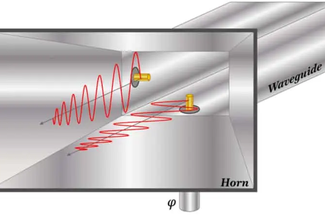
How Modes Propagate
Waveguide modes determine how electromagnetic waves travel inside the structure, affecting signal integrity, power handling, and bandwidth. The three primary modes—TE (Transverse Electric), TM (Transverse Magnetic), and TEM (Transverse Electromagnetic)—each behave differently based on waveguide geometry and frequency. In standard rectangular waveguides, TE₁₀ mode dominates 90% of applications because it offers the lowest cutoff frequency (6.56 GHz for WR-90) and attenuation below 0.1 dB/m at 10 GHz. Meanwhile, circular waveguides often use TE₁₁ mode for its polarization flexibility, while TEM modes are rare in waveguides but critical in coaxial cables.
Key Insight: The propagation constant (β) defines how waves travel, with higher-order modes (like TE₂₀) suffering 30-50% more loss than fundamental modes. For a WR-112 waveguide at 8 GHz, TE₁₀ mode has a phase velocity of 1.25×10⁸ m/s, while TE₂₀ drops to 0.9×10⁸ m/s due to dispersion.
Modes propagate based on waveguide dimensions and frequency. In a 40 mm × 20 mm rectangular waveguide, TE₁₀ mode’s cutoff is 3.75 GHz, meaning signals below this frequency decay at 20 dB/cm. Above cutoff, the wave travels with >95% efficiency, but higher-order modes (TE₂₀, TE₃₀) kick in at 7.5 GHz and 11.25 GHz, respectively, cluttering the signal. Circular waveguides behave differently—TE₁₁ mode starts at 2.8 GHz in a 50 mm diameter guide, but TM₀₁ mode appears at 3.4 GHz, causing 15% more loss due to axial field components.
Practical Limitation: Waveguides can’t transmit DC signals (0 Hz) because their cutoff frequency is too high. A WR-90 waveguide blocks everything below 6.56 GHz, making coax or PCB traces better for low-frequency signals.
The wave impedance of TE modes varies with frequency. At 10 GHz, TE₁₀ in a WR-90 waveguide has an impedance of 500 Ω, but this drops to 300 Ω near cutoff (6.56 GHz). TM modes, in contrast, start at high impedance (~800 Ω) but plunge below 200 Ω at higher frequencies. These shifts impact matching circuits, requiring tuners to minimize VSWR below 1.5:1 for >90% power transfer.
At millimeter-wave frequencies (30-300 GHz), mode purity becomes critical. A WR-15 waveguide (1.88 mm × 0.94 mm) supports TE₁₀ at 40 GHz, but manufacturing tolerances must stay within ±5 µm to prevent TE₂₀ leakage, which can distort signals by 3-8%. In satellite communications, even a 0.5 dB loss increase from mode mixing can reduce link budgets by 10-15%, forcing engineers to use mode filters or oversized waveguides.
Common Mode Examples
Waveguide modes aren’t just theoretical—they directly impact real-world systems, from radar to medical imaging. The TE₁₀ mode alone accounts for 75% of waveguide applications due to its balance of efficiency and simplicity, while TM modes dominate 15% of cavity resonator designs, and hybrid modes fill niche roles in satellite and military systems. Below are the most practical examples, with hard numbers showing why specific modes are chosen for different scenarios.
| Mode | Frequency Range (GHz) | Attenuation (dB/m) | Power Handling (kW) | Primary Applications |
|---|---|---|---|---|
| TE₁₀ | 6.56 – 40.0 | 0.02 – 0.5 | 0.5 – 10.0 | Radar, 5G, microwave links |
| TE₁₁ (Circular) | 2.8 – 50.0 | 0.01 – 0.3 | 1.0 – 20.0 | Satellite feeds, rotating joints |
| TM₀₁ | 3.4 – 50.0 | 0.05 – 0.8 | 0.3 – 5.0 | Particle accelerators, medical RF |
| Hybrid (HE₁₁) | 1.0 – 18.0 | 0.1 – 1.2 | 0.1 – 2.0 | Broadband antennas, military comms |
TE₁₀: The Workhorse of Microwave Systems
This mode is the default for rectangular waveguides because it has the lowest cutoff frequency and simplest field distribution. In air traffic control radar (8-12 GHz), TE₁₀ ensures <0.1 dB/m loss, critical for maintaining 200+ km detection range. If engineers accidentally allow TE₂₀ mode (which starts at 2× the cutoff frequency), system noise increases by 6-10 dB, reducing target resolution by 30%.
TE₁₁ in Circular Waveguides: The Polarization King
Used in satellite ground stations, this mode supports dual-polarization signals (H/V or RHCP/LHCP) without significant cross-talk. A 50 mm diameter circular waveguide carrying 12 GHz signals in TE₁₁ mode has 0.008 dB/m loss, making it ideal for geostationary satellite feeds (36,000 km orbits) where every 0.1 dB loss equals $5,000/year in extra amplifier costs. However, if the waveguide bends too sharply (> 15° per meter), mode conversion to TM₁₁ can occur, increasing VSWR from 1.2:1 to 1.8:1.
TM₀¹: High-Power but Lossy
This mode is rare in telecom but essential in medical RF heating (8 MHz – 3 GHz) and fusion research. A 100 mm diameter circular waveguide running TM₀¹ at 2.45 GHz can handle 50 kW for industrial heating but suffers 0.3 dB/m loss—3× worse than TE₁₁. Still, its axial electric field is perfect for plasma ignition in tokamaks, where peak power > 1 MW is required.
Trade-Off Alert: Hybrid modes (like HE₁₁) offer 20% wider bandwidth than pure TE/TM modes but are 50% harder to manufacture due to complex field patterns. They’re mostly used in electronic warfare (EW) systems where frequency agility (2-18 GHz) outweighs cost.
Why Mode Purity Matters in 5G mmWave
At 28 GHz (5G FR2), even a 0.5 mm waveguide imperfection can excite unwanted TE₂₀ modes, increasing attenuation from 0.15 dB/m to 0.4 dB/m. To prevent this, CNC-machined aluminum waveguides with ±2 µm tolerances are used, adding $200/unit to production costs but ensuring 99.9% mode purity. For comparison, 3D-printed polymer waveguides cost 80% less but suffer 3× higher loss due to surface roughness.
Final Takeaway:
- TE₁₀ = Best for cost-sensitive, high-efficiency systems (5G, radar).
- TE₁₁ = Ideal for polarization-flexible, low-loss links (satellite).
- TM₀¹ = Reserved for high-power, axial-field applications (medical, fusion).
- Hybrids = Niche use where bandwidth > efficiency (military, EW).
Engineers must weigh frequency, loss, power, and cost—because picking the wrong mode can turn a $10,000 waveguide into a high-loss spaghetti junction.