Table of Contents
Mathematical Explanation
-
One interesting point to consider is that electromagnetic waves, such as these used in communication systems, follow Maxwell equations.
Transverse electromagnetic wave
-
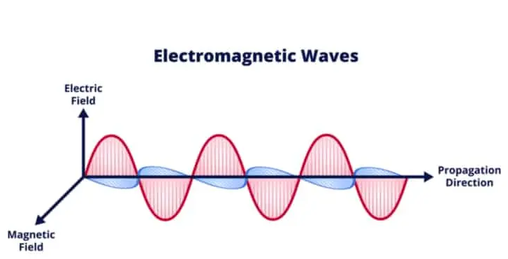
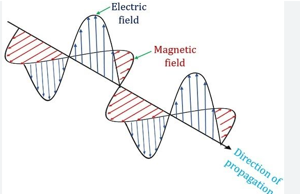
One class of waves, which different to others by the property that in both of its fields electric $[E]$ and magnetic $[H]$ are perpendicular to direction, is TEM: transverse electromagnetic wave.
-
TEM waves have many benefits that make them desired in particular applications, because of low dispersion and constant phase velocity.
Waveguides
-
Waveguide is a device that guides electromagnetic wave from beginning to the end the end of its length.
-
Nevertheless, the concept by which waveguides operate force waves, especially TEM waves not to be allowed to propagate through the device.
-
Waveguide’s nature creates the boundary conditions that guide the way the electromagnetic fields should behave within it.
Boundary Conditions
-
Electromagnetic fields in the waveguide must fall to satisfy some necessary conditions related to waveguide surfaces.
-
In the metallic waveguide, field’s electric must be tangential while magnetic field must be normal to theconductive surfaces.$^{1}$
TEM wave propagation
-
TEM waves are transverse with all fields being perpendicular to the direction of propagation.
-
In a rectangle of a circular cross section, it is impossible to have whole both electric and magnetic fields such that they are non-zero according to the boundary conditions.
-
Therefore, TEM fields cannot be able to propagate.$^{2}$
Physical insight
-
It is a manifestation of inability of an electromagnetic wave to propagate as TEM in the presence of an enclosed metallic waveguide.
-
Energy carried in the TEM fields is energy is distributed/accommodated equally sharing the whole cross-section medium.
-
However, boundary conditions do not allow this accommodation. Rather the fields redistribute in the way inconsistent with the TEM form and therefore energy is lost.
Exceptions
-
The only exception, where the TEM waves are permited to propagate is the coaxial cable.
-
The field is accommodated in the cable open cross-section entirely perpendicular. The coaxial cable has a the inner and outer conductors that has constant phase velocity and characteristic impedance that can support the high frequency of signal. $[3]$
Comparative analysis
-
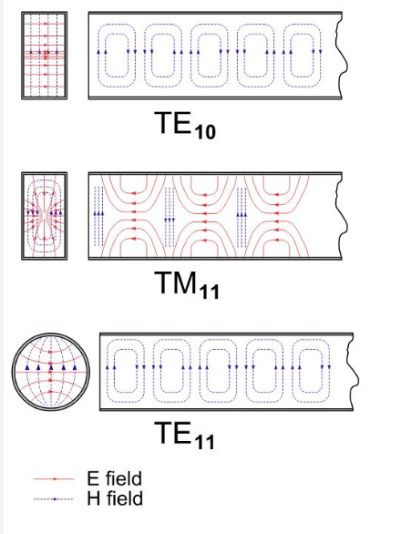
TE and TM waves have the capability of passing through since it is not the case as TEM idea.
-
TE and TM are two types of field which can either traverse electricity or the magnetic.
-
They can pass to work in the waveguide due to the interaction while in waveguide adequate fitness is allowed.
 Critical Frequency and Wavelength
The concepts of critical frequency and wavelength play an important role in the design of efficient waveguides and communication systems. The critical frequency for a waveguide is defined as the lowest frequency at which a mode can propagate through it without being excessively attenuated , and the critical wavelength is the corresponding wavelength of the critical mode. The critical frequency is essential for designing microwave and optical waveguides as for all frequencies below the critical one the signal is heavily attenuated.
The critical frequency is the lowest frequency at which a mode can propagate through a waveguide with very little attenuation or none. Therefore the critical frequency describes the operational bandwidth of the waveguide . By possessing the information about the critical frequency required by the mode, the designer can determine the frequency range for which this waveguide is efficient.
If a rectangular guide for TE modes of the dominant mode pair is considered and its dimensions are given as a=2 cm and b=1 cm, the formula to determine the critical frequency for the dominant mode of n=1, m=0 is the following:
Thus, tis frequency can be calculated by using the given dimensions and the speed of light in the vacuum: 2 x 10 8 m/s . The critical frequency for the TE01 mode appears to be around 7.5 GHz which means that any signal with the frequency below that would be heavily attenuated and would be useless for transmission through these waveguides.
The critical wavelength is connected to the critical frequency by the inverse relationship formula and describes the physical parameters of the waveguide at the same time. The waveguide with larger dimensions can support lower critical frequencies of the transmission which is very useful for wider bandwidth transmission.
The critical wavelength is very important for the design of the optical fibers because it defines the modal dispersion and hence the bandwidth and information capacity of the fiver . The standard single-mode fiber with the core diameter of 8.3 micrometers features the critical wavelength close to the 1.3 micrometers. This wavelength is in the near infrared region and the multimode fibers have the critical wavelength of 0.83 micrometers in the visible part of the spectrum. This is useful for telecommunications because the silica glass used in the construction of optical glass has the minimal dispersion and attenuation in that region. Selecting the best wayguide or fiber components frequency characteristics can be achieved.
Mode Cut-off Conditions
Modes cut-off conditions are an essential concept in the context of waveguides designing and analysis. These conditions describe the minimum frequency or maximum wavelength with which a specific mode ��m may be propagated through the waveguide. The understanding of this phenomena is crucial for achieving high efficiency of wave propagating and attaining minimum attenuation and transmitting losses in waveguide systems. The above-mentioned conditions have a significant impact on waveguides and optical fibers design and require consideration related to operating frequency, mode, and material properties. In the context of the microwave waveguides focusing on the TE and TM modes cut-off frequency , the cut-off frequency for the ��ℎmth mode significantly impacts waveguide design and propagation.
Computational Details
The above-mentioned cut-off frequency is impacted by the waveguide’s properties and the attributes of the materials applied. Rectangular microwave waveguide supporting TE and TM modes may be described by the cut-off frequency formula:
��=�2(��)2+(��)2fcmostyles ./fcmostyle=2c(am)2+(bn)2,.
where fcmostyles is the cut-off frequency of the TE mode, and its square is given as 2, �a and �b are the dimensions of the guide cross-section, �m and �n are mode-image numbers, and the waves propagate in the �m direction for TE modes . It may be seen that the smaller the guide, the higher the cut-off frequency, and the larger the mode number, the higher the cut-off frequency. Without a significant loss of generality, it may be stated that for a rectangular guide 2 cm � 1 cm built for TE10 propagating mode, the cut-off frequency would be 7.5 GHz, and for TE20 or TM11 operating mode cut-off frequency it would be a higher value.
Cut-off Conditions Implications
Overall, cut-off conditions for TE and TM modes significantly impact waveguide design. In many applications like satellite communications and radar, a designer objective might be to build a specific range or select a waveguide size and shape that ensures that the operating frequency is significantly above the cut-off frequency for the dominant mode and significantly below the cut-off frequency for all other modes . Thus, mode dispersion and attenuation are minimized, thus ensuring the maintenance of signal quality when transmitted over long distances.
Optical Fibers and Modes Cut-off
For optical fibers like microwave waveguides, the cut-off wavelength is an equivalent to the above-described cut-off frequency. For instance, the cut-off wavelength for the second-order mode in a single-mode fiber is the upper limit where the fiber continues to propagate only in one mode. This is important for high-speed data transmission systems because silica glass produces minimum modal dispersion and attenuation. The standard single-mode fiber has a core diameter of 8 microns, so its cut-off wavelength is approximately 1.3 microns, and the fiber operates around 1.55 microns for telecommunications systems.
Practical Value
Cut-off conditions require intensive considerations when designing a waveguide or fiber system for a specific application. The main parts of this process include material choice and definition of gratings electromagnetic properties, accurate waveguide or fiber dimension definition, and an appropriate selection of operating frequency or pass-through light wavelength ensuring the sole dedicated mode being propagation through the system.
Implications of TEM Wave Limitations
The effect of the limitations on even mode requirements in waveguides has several implications on various electromagnetic systems and their designs. This affect the design and performance of microwave, optical, and radio frequency systems. Therefore, engineers require an understanding of these effect to make an informed decision on the design and selection of waveguides and transmission lines.
-
Design and Material Selection
The limitations of TEM waves imply that designers must consider other types of waveguides and transmission lines if they require the propagation of TEM mode. This occurs because TEM waves are not able to propagate in a waveguide with a closed conducting surface. People use coaxial cables as the structure of the TEM waves is open and is to coaxial the cables in its structure. The characteristic impedance of a coaxial cable with an inner conductor radius of 0.5 mm and an outer conductor radius of 2.5 mm at 1 GHz is 50 . This type of the cable is used in RF systems due to its high efficiency in reducing signal losses. In addition, the use of two conductors in close proximity helps minimize the inductive and capacitive reactance. It also reduces the cross-talk between adjacent lines.
-
Signal Integrity and Bandwidth
The limitations of TEM mode imply that TEM waves cannot propagate in all types of waveguides and transmission lines. This affects the integrity of the signal and the bandwidth. In high speed digital and analog systems, a broad bandwidth with minimal distortions is required. Therefore, even mode requirements affect the use of other transmission lines, such as optical fibers and microstrip lines. Coaxial cables are used as broadband internet and satellite communication systems . Comparatively, optical fibers, although not able to propagate TEM waves, require the use of TE and TM to propagate light waves. The single-mode optical fiber is designed to operate at the 1.55 micrometer wavelength. Therefore, it has an over 60 GHz bandwidth. This is useful in the telecommunications systems where long distances are involved, and high data rates are required.
-
System Efficiency and Cost
The limitations of TEM have the effect of the target waveguide and transmission line. Primarily, this depends on the type of fetish that can satisfy the requirements of TEM mode. Especially for RF systems, the characteristics of coaxial cables are most valuable. This is despite their bulkiness and higher costs. For optic systems, the cost-effectiveness of the optical fibers and their low attenuation values make a valuable over other choices. Therefore, decisions on system materials and cost are determined by even-mode limitations. For example, the deployment of a citywide network of coaxial cables may cost 20% more than the use of optical fibers. This is driven by the higher material and installation cost of coaxial cables. Additionally, the higher attenuation values of coaxial cables require more amplifiers and repeaters in a form of signal system in use. These devices add to the system cost.