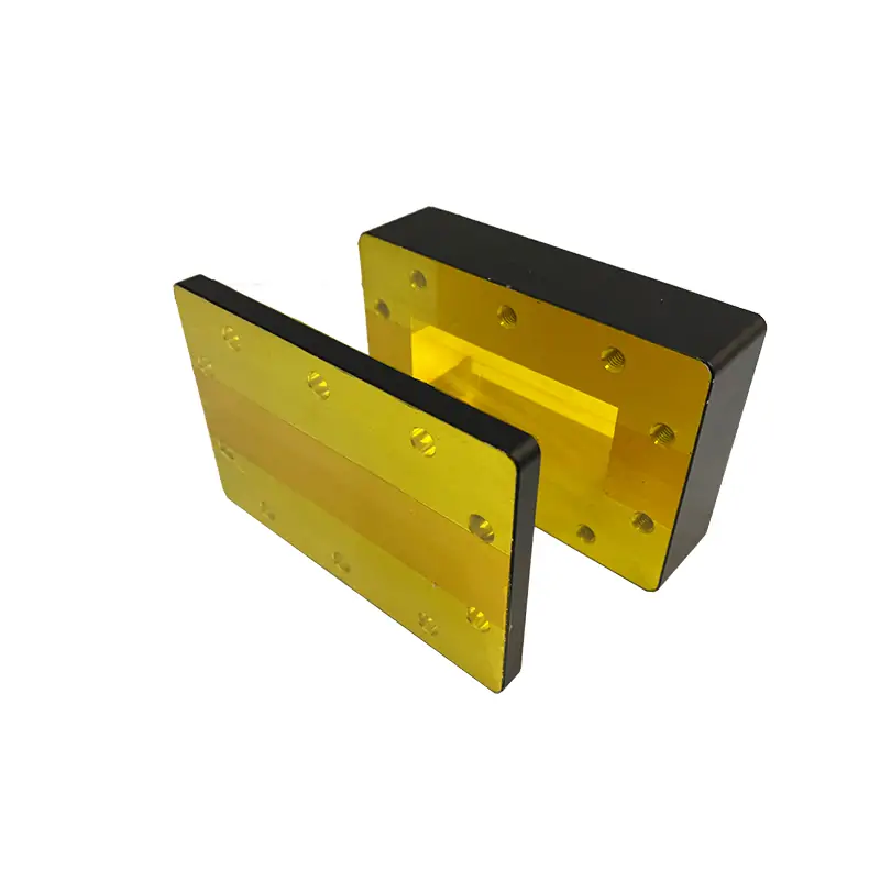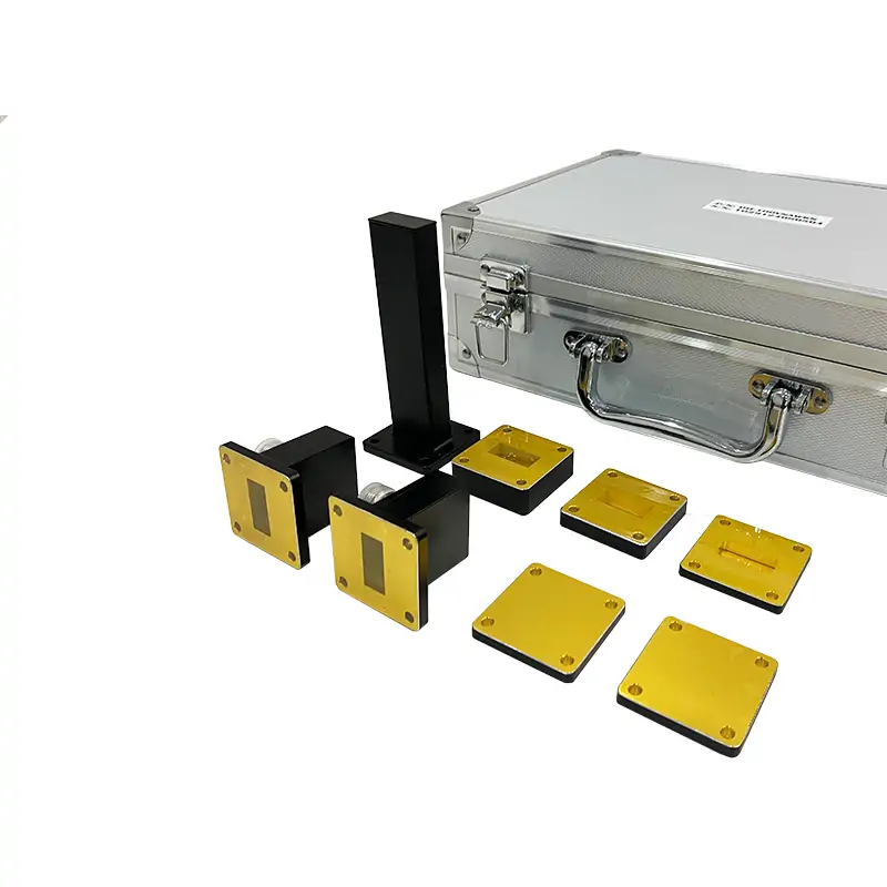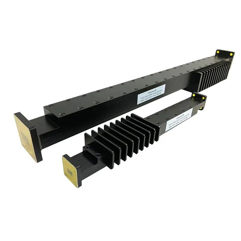
Precision Fixed Attenuator
Designed for high-power RF systems, the Dolph Microwave Precision Fixed Attenuator delivers ultra-low VSWR (≤1.15:1) and exceptional accuracy (±0.1 dB) across 0.84–40 GHz (WRD840 to WRD110). With attenuation values from 3 dB to 40 dB and in-band flatness of ±1.5 dB, it ensures reliable signal control in radar, satellite communications, and 5G base stations. Built for demanding environments, it handles up to 100 kW average power (model-dependent) and features corrosion-resistant aluminum or Al/Cu construction with Surtec 650 coating.
Product Overview
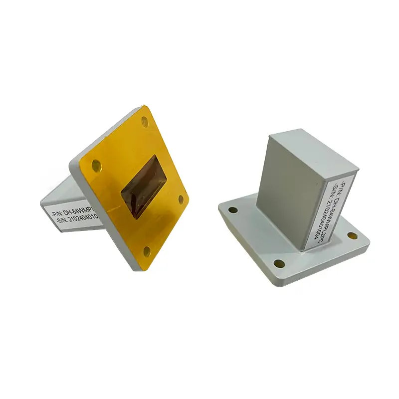
Dolph Microwave’s Double Ridged Precision Fixed Attenuator delivers ultra-low VSWR (≤1.15:1) and exceptional attenuation accuracy (±0.1 dB) across a broad frequency range (0.84 GHz–40 GHz). Designed for high-power applications up to 100 kW CW, these attenuators support precise signal control in radar, satellite communications, and 5G infrastructure. Available in waveguide sizes from WRD840 to WRD180, with customizable attenuation values (3–40 dB) and ±1.5 dB in-band flatness, they ensure reliability in mission-critical RF systems.
Key Features
- Ultra-Low VSWR: ≤1.15:1 across all models.
- Broadband Performance: 0.84 GHz–40 GHz (WRD840 to WRD180).
- High-Power Handling: Up to 100 kW average power (model-dependent).
- Precision Attenuation: ±0.1 dB accuracy and ±1.5 dB flatness.
- Robust Construction: Aluminum or Al/Cu composite with Surtec 650 anti-corrosion coating.
- Customizable: Attenuation up to 40 dB and optional flange configurations (flat/grooved).
Applications
- Radar Systems: Signal leveling for military and aviation radar arrays.
- Satellite Communications: Power management in C/X/Ku-band SATCOM links.
- 5G Networks: Base station testing and mmWave signal conditioning.
- Test & Measurement: Calibration and RF signal integrity validation.
- Wireless Infrastructure: DAS (Distributed Antenna Systems) optimization.
| MODEL | FREQ. RANGE (GHz) | WG SIZE | VSWR Max. | ATT. (dB) | FREQ. RESPONSE (dB) | AVG POWER CW (KW) | FLANGES TYPE | MATERIAL | FINISH | DATASHEET | ||
| COVER | GROOVED | |||||||||||
| DH-840DRWFA… | 0.84-2.0 | WRD840 | 1.15:1 | 3-40 | ±1.5 | 100 | FPWRD840U24 | FMWRD840U24 | Al | Chromate/Painted | DWG | STEP |
| DH-150DRWFA… | 1.5-3.6 | WRD150 | 1.15:1 | 3-40 | ±1.5 | 100 | FPWRD150D24 | FMWRD150D24 | Al | Chromate/Painted | DWG | STEP |
| DH-200DRWFA… | 2.0-4.8 | WRD200 | 1.15:1 | 3-40 | ±1.5 | 100 | FPWRD200D24 | FMWRD200D24 | Al | Chromate/Painted | DWG | STEP |
| DH-250DRWFA… | 2.6-7.8 | WRD250 | 1.15:1 | 3-40 | ±1.5 | 100 | FPWRD250D30 | FMWRD250D30 | Al | Chromate/Painted | DWG | STEP |
| DH-350DRWFA… | 3.5-8.2 | WRD350 | 1.15:1 | 3-40 | ±1.5 | 100 | FPWRD350D24 | FMWRD350D24 | Al | Chromate/Painted | DWG | STEP |
| DH-475DRWFA… | 4.75-11.0 | WRD475 | 1.15:1 | 3-40 | ±1.5 | 100 | FPWRD475D24 | FMWRD475D24 | Al | Chromate/Painted | DWG | STEP |
| DH-500DRWFA… | 5.0-18.0 | WRD500 | 1.15:1 | 3-40 | ±1.5 | 100 | FPWRD500D36 | FMWRD500D36 | Al | Chromate/Painted | DWG | STEP |
| DH-580DRWFA… | 5.8-16.0 | WRD580 | 1.15:1 | 3-40 | ±1.5 | 100 | FPWRD580D28 | FMWRD580D28 | Al | Chromate/Painted | DWG | STEP |
| DH-650DRWFA… | 6.5-18.0 | WRD650 | 1.15:1 | 3-40 | ±1.5 | 100 | FPWRD650D28 | FMWRD650D28 | Al/Cu | Chromate/Painted | DWG | STEP |
| DH-700DRWFA… | 7.0-18.5 | WRD700 | 1.15:1 | 3-40 | ±1.5 | 100 | FPWRD700D26 | FMWRD700D26 | Al/Cu | Chromate/Painted | DWG | STEP |
| DH-750DRWFA… | 7.5-18.0 | WRD750 | 1.15:1 | 3-40 | ±1.5 | 100 | FPWRD750D24 | FMWRD750D24 | Al/Cu | Chromate/Painted | DWG | STEP |
| DH-110DRWFA… | 11.0-26.5 | WRD110 | 1.15:1 | 3-40 | ±1.5 | 50 | FPWRD110C24 | FMWRD110C24 | Al/Cu | Chromate/Painted | DWG | STEP |
| DH-180DRWFA… | 18.0-40.0 | WRD180 | 1.15:1 | 3-40 | ±1.5 | 50 | FPWRD180C24 | FMWRD180C24 | Al/Cu | Chromate/Painted | DWG | STEP |
| Part Number Guide: DH-840DRWFA30PMA100 "840DR"—Waveguide Size | WRD840 "WFA"—Waveguide Type | Precision Fixed Attenuator "30"— Attenuator Value | 30 dB "P"— Flange Type | Rectangular Flat "M"— Flange Type | Rectangular Grooved "A/C"— Material | Aluminium, Cu "100"— Power Rating | 100 W CW. |
||||||||||||
| Note: All Dolph-MW models include an surtec/corrosion protection treatment and are painted flat black. Flanges are unplated, polished and surtec. Other finishes and paint colors are available upon request. |
||||||||||||