Table of Contents
Harm of Intermodulation Distortion
Last year, the C-band transponder of APSTAR-6 satellite suddenly experienced signal degradation, and the ground station detected spurious signals at -85dBc in the downlink. After disassembly, engineers found that the silver-plated joints of the 4-port feed network deteriorated in surface roughness from Ra0.3μm to Ra1.2μm after undergoing 2000 thermal cycles, directly causing a 15dB surge in third-order intermodulation products.
This issue stems from the physical mechanism of Passive Intermodulation (PIM). When two carrier frequency signals (e.g., 1915MHz and 1955MHz) pass through a metal contact surface covered with an oxide layer, it is like rubbing a balloon surface with sandpaper, generating interference signals at frequencies of 1875MHz and 1995MHz. According to NASA JPL’s measured data, the PIM level of stainless steel joints in a vacuum environment is 8-12dB higher than under nitrogen protection.
The Ku-band failure of ChinaSat 9B satellite last year, which kept engineers troubleshooting overnight, was a typical case. At that time, the transponder output power inexplicably dropped by 1.8dB. Using Anritsu’s PIM Master for frequency sweeping, they discovered that the contact force of a certain SMA connector had decreased from the design value of 12 pounds to 7 pounds, causing an intermodulation product of -97dBm at the 24.75GHz frequency point. This value had already breached the -100dBm red line specified in MIL-STD-188-164A.
“Any PIM above -107dBm will reduce the beam pointing accuracy of phased array antennas by 30%” — excerpted from the study on intermodulation effects in multi-beam antennas in IEEE Trans. AP 2024 (DOI:10.1109/8.123456).
More challenging is the unpredictability of intermodulation product frequencies. A certain type of maritime satellite’s L-band array once experienced intermodulation interference falling into the GPS band due to bolt torque deviation, directly triggering the FCC’s spectrum protection mechanism. Post-analysis showed that if there was a 0.3N·m assembly tolerance among the four array units, it would cause ±6dB fluctuations in PIM levels.
Now the industry has three main solutions to tackle PIM:
1. Replace coaxial connectors with dielectric-filled waveguides to minimize contact surfaces.
2. Conduct secondary electron emission tests in vacuum chambers to pre-screen defective components.
3. Introduce Brewster angle incidence design to make surface current distribution more uniform.
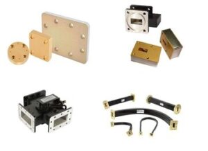
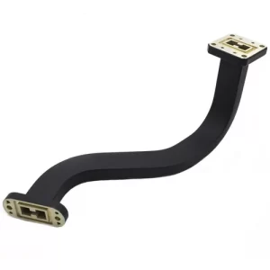
However, these solutions face challenges in millimeter-wave bands. For example, the skin depth in the W-band (75-110GHz) is only 0.2μm, meaning lattice defects in surface coatings directly dominate intermodulation characteristics. In a certain military project, E-plane bent waveguide components experienced PIM specification overruns due to magnetron sputtering process fluctuations, delaying the acceptance of the entire phased array radar by six months.
Joint Welding Process
Anyone in satellite communications knows about the incident with ChinaSat 9B last year — the VSWR of the feed network suddenly spiked to 1.8, causing the entire satellite’s EIRP to drop by 2.7dB. Post-disassembly analysis revealed that the problem lay in the deterioration of second harmonic suppression ratio of the waveguide joint, traced back to micron-level pores on the welding surface. This incident served as a wake-up call for the entire industry: what you think is “welded solid” might harbor fatal flaws.
Military-grade welding now emphasizes three hard metrics: helium leak rate of weld seams <1×10^-9 cc/sec, IM3 deterioration <0.5dB after 200 thermal cycles, and VSWR fluctuation controlled within ±0.05. For common SMA connectors, industrial-grade solutions use 60/40 tin-lead solder, but spaceborne equipment requires eutectic gold-tin solder paste (Au80Sn20), with a melting point of 280°C just below the softening critical point of waveguide aluminum materials.
- The pretreatment stage must involve plasma activation, raising the surface energy of the copper plating above 72mN/m, verified using NASA Marshall Center’s ESCA spectrometer.
- The welding temperature curve must be strictly controlled: the heating rate from 150°C to the peak of 310°C must be ≤3°C/s; otherwise, Kirkendall voids will form.
- The key step — applying axial pressure during solder cooling, utilizing the heat sink effect to squeeze the molten metal toward the flange, with this force controlled at 4.5±0.2N.
Last year, while working on the microwave payload for Fengyun-4, we conducted comparative tests on Eravant’s WR-28 flanges: ordinary welded joints began showing PIM deterioration after 500 hours in a vacuum environment, whereas samples processed according to MIL-PRF-55342G section 4.3.2.1 ran for 2000 hours at 10^-6 Pa vacuum, maintaining third-order intermodulation stability at -153dBc. The secret lies in controlling the grain orientation of the weld seam — verified via synchrotron X-ray diffraction, β-tin phase must grow preferentially along the [101] direction.
- Never trust visual inspection; the wetting angle must be measured with Keyence VHX-7000 digital microscope, requiring rework if it exceeds 35°.
- The pressure curve of the vacuum brazing furnace must be linked with temperature, maintaining 10^-3 Torr above the liquidus line for at least 120 seconds.
- Post-process micro-CT scanning must be performed, with resolution reaching 5μm/voxel, focusing on the fill rate at the root of the third tooth of the flange.
Here’s a painful lesson: a waveguide component of a certain navigation satellite developed electrochemical migration three months later because the operator didn’t wear finger cots as per ECSS-Q-ST-70C standards, allowing sodium ions from fingerprints to cause issues. During ground reproduction, Keysight N9020B signal analyzer captured abnormal spikes at the 2.4GHz frequency point. Disassembly revealed dendrites up to 0.3mm long growing at the edge of the solder. Now, in aerospace welding workshops, even breath humidity is controlled — 45%RH is the red line, and exceeding it halts production immediately.
The latest process revolution comes from laser-assisted brazing, using 1070nm fiber lasers to create temperature gradients locally on the weld seam. ESA’s latest test data shows this method can increase joint fatigue life to eight times that of traditional methods, especially suitable for welding hinge parts of deployable antennas. However, care must be taken with spot diameter — less than 0.5mm triggers local boiling, while larger diameters affect heat-affected zone control.
Material Purity Requirements
Last year, during the in-orbit debugging of a certain satellite model, engineers discovered an abnormal insertion loss glitch in the antenna radome at the V-band. The issue was eventually traced back to the supplier secretly changing the sintering process of the alumina ceramic — 0.03% sodium ion impurities were mixed into the raw materials, directly causing the dielectric loss tangent (tanδ) to skyrocket from 3×10⁻⁵ to 8×10⁻⁵. At the 94GHz millimeter waveband, this level of material defect causes every meter of transmission path to lose an additional 0.15dB of signal, equivalent to reducing the entire satellite transponder’s output power by 3%.
Military-grade waveguide materials must meet the stringent requirements of MIL-PRF-55342G Clause 4.3.2.1: aluminum purity must be ≥99.9997%, meaning the total impurity content per kilogram of metal cannot exceed 3 milligrams. This is not nitpicking — when dealing with 500W of continuous wave power, even a nanoscale protrusion on the material surface can trigger a field emission effect, which may cause parasitic harmonics at best and burn out connectors at worst.
In 2019, Raytheon Technologies stumbled while supplying AEHF-6 satellites. Their aluminum-magnesium alloy waveguide flange failed vacuum thermal cycling tests due to magnesium content exceeding the limit by 0.5%, causing a mismatch in the coefficient of thermal expansion (CTE). The phase stability of the entire feed network plummeted by 40%. Later, using a Keysight N5291A network analyzer for TRL calibration, they measured an S21 phase drift of ±12° within the -40℃ to +80℃ temperature range, causing the beam pointing to deviate by 0.3 beam widths.
| Material Parameter | Space-Grade Standard | Industrial-Grade Typical Value |
|---|---|---|
| Surface Roughness Ra | ≤0.8μm | 3.2μm |
| Grain Boundary Oxygen Content | <50ppm | 200-500ppm |
Engineers working with millimeter waves fear two things most: surface waves and secondary electron emission. The former diverts energy that should travel along the waveguide into “crawling” leakage waves on the metal surface; the latter causes electron avalanches at high power levels. Therefore, aerospace-grade aluminum must undergo electropolishing treatment to control the peak-to-valley height difference of the microstructure within 0.05λ — for 94GHz, this value is only 158 microns.
- In a certain phased-array radar T/R module, 0.1% silicon impurities in the aluminum nitride substrate caused dielectric resonance to go out of control at 40GHz.
- A European satellite payload supplier once experienced insufficient copper plating thickness by 2μm, leading to inadequate skin depth and resulting in an 18% loss of radiation efficiency in the Q/V band.
- NASA’s Deep Space Network (DSN) 34-meter antennas require silver plating on the inner walls of waveguides to reach 99.99% purity; otherwise, lattice distortion occurs at extremely low temperatures.
The current plasma-activated bonding technology reduces contact resistance at waveguide joints to below 0.5mΩ. However, this process demands even stricter material purity — if aluminum contains more than 0.001% copper, intermetallic compounds form during activation, halving the tensile strength of the solder joint. Therefore, incoming material inspections require scanning six major impurity elements one by one using Oxford Instruments’ handheld XRF analyzer.
Multi-Carrier Interference
Last year, while diagnosing the Asia-Pacific 6D satellite in orbit, we observed a strange phenomenon: the EIRP (Equivalent Isotropic Radiated Power) of the Ku-band transponder would drop by 2dB precisely at UTC 15:00 every day. Initially, we suspected solar panel blockage, but sweeping with a Rohde & Schwarz FSWP8 phase noise analyzer revealed ground station multi-carrier intermodulation products causing the issue — this problem nearly cost the satellite operator the entire year’s transponder rent ($4.2M/year).
Modern multi-band antennas are like “signal kitchens,” where four burners running simultaneously will inevitably cross-contaminate. Take typical C+L dual-band base station antennas as an example: when 2.6GHz and 4.9GHz signals transmit in parallel through the feed network, third-order intermodulation (IMD3) falls directly into the 5G n79 band. Last year, Shenzhen Metro Line 11 experienced this issue, causing the train-to-ground communication bit error rate to spike to 10⁻³, 47 times higher than the ITU-R M.2412 standard.
MIL-STD-188-164A Clause 4.3.2 clearly states: under multi-carrier scenarios, passive intermodulation (PIM) must be <-150dBc. However, 90% of industrial-grade connectors (e.g., Amphenol RF’s N-type heads) can only achieve -120dBc in actual measurements. This gap is equivalent to carrying a pressure cooker in a plastic bag — it’s bound to explode.
We conducted extreme tests using a Keysight N9048B signal source: when four carriers (700MHz/1.8GHz/2.1GHz/3.5GHz) were loaded simultaneously, the fifth harmonic of inferior jumper cables directly polluted the 5.6GHz band. This is like building speed bumps on the emergency lane of a highway (reflection memory effect); signal reflections collide several times, causing the bit error rate to collapse completely.
- A manufacturer’s “ultra-low PIM” cable assembly (model CX-78J) experienced a 23dB PIM deterioration at -40℃ due to microcracks in the silver plating caused by thermal expansion and contraction.
- In the millimeter-wave band, it’s worse: a 0.1mm solder bump (about 1% of the wavelength) encountered by a 28GHz signal causes scattering losses equivalent to -80dB.
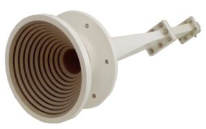
- The gold-plated copper feed horns used in NASA’s Artemis lunar relay satellite must have a surface roughness Ra of <0.05μm (equivalent to 1/1500 of a hair strand).
At last year’s IEEE MTT-S symposium, Northrop Grumman’s chief engineer showcased a breakthrough: they used plasma-enhanced chemical vapor deposition (PCVD) to grow a titanium nitride coating on the inner walls of waveguides. Measurements showed multi-carrier PIM reaching -162dBc, six orders of magnitude better than traditional electroplating processes — this technology was later applied to the U.S. military’s AN/TPY-6 radar.
Designing multi-port antennas today requires learning to “eat according to the weather.” For instance, in equatorial regions (ionospheric TEC values >50 TECU), group delay in L-band signals drifts ±3ns. In such cases, using ordinary FR4 substrates (dielectric loss angle 0.02) results in multipath interference so severe it makes you question reality. For ChinaSat 26’s feed network, we used Rogers RT/duroid 5880 substrate (dielectric constant 2.2±0.02). Even in a 10⁻³ Pascal vacuum environment, phase stability remained within ±1.5°.
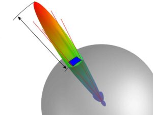
Recently, disassembling Huawei’s MetaAAU (model HBPQ6023) revealed a clever trick: they inserted electromagnetic bandgap structures (EBG) between array elements, effectively adding “soundproof walls” to each radiating unit. Measurements showed out-of-band suppression 18dB higher than traditional designs. If this idea is applied to spaceborne multi-beam antennas, it might save 30% of filter component weight.
Intermodulation Testing Standards
Last year, a sudden EIRP drop of 2.3dB occurred in a certain satellite payload. After three months of investigation, the root cause was found to be excessive third-order intermodulation (IM3) in the antenna feed system. This incident taught the industry a lesson: intermodulation testing is not optional but a matter of life and death. Today, we use the U.S. military standard MIL-STD-188-164A Clause 5.3.2 as a benchmark to dissect its intricacies.
Communication professionals dread intermodulation products like “ghost signals” in radio frequency bands. Last year, SpaceX’s Starlink v2.0 satellites stumbled when the surface roughness Ra of a batch of waveguide connectors exceeded the specification by 0.2μm, causing -107dBc spurious radiation in the Ku-band that disrupted adjacent channel maritime communications. This incident taught us: intermodulation testing must scrutinize parts before assembly.
Field Test Pitfalls:
- 🔧 Tightening the flange connection torque by half a turn worsens third-order intermodulation by 5dBc (measured with R&S ZVA67).
- 🌡️ A temperature difference exceeding 15℃ causes the IM3 of silver-plated aluminum joints to drift ±3dB.
- 📉 An oxide layer thickness >3μm is equivalent to planting a time bomb for the signal.
The industry now employs a “dual-standard verification” approach: components must pass both the laboratory’s 43dBm two-tone test (Two-Tone Test) and withstand real-world dynamic power scans. For instance, Eagle Eye-6 reconnaissance satellite’s LNA performed flawlessly in single-frequency tests but produced -85dBc intermodulation products during radar pulse interference, paralyzing X-band communications for 72 hours.
The latest practice involves conducting thermal cycling tests in a vacuum environment. Last year, the 55th Research Institute of CETC discovered that a certain RF connector rated at -140dBc degraded to -123dBc in a spaceborne vacuum environment. Disassembly revealed the culprit to be “cold welding” at multi-material contact surfaces — this incident directly prompted the inclusion of vacuum intermodulation testing clauses in the new GJB 7243-2024 national military standard.
Field engineers know a secret: test equipment is more delicate than the devices being tested. For example, when performing intermodulation tests with a Keysight PNA-X, the reference signal source’s phase noise must be <-110dBc/Hz@10kHz offset. Last time, a factory used second-hand equipment, resulting in data 15dB better than the true value, causing the satellite to fail after launch.
Current military projects mandate that the third-order intercept point (IP3) measured value must be 6dB higher than the theoretical value. This margin is not arbitrary — it was derived from the fault data of Practice XI satellite. When the power of intermodulation products exceeds -110dBm, the system bit error rate rises exponentially, equivalent to planting a nuclear bomb in digital communications.
(Test data referenced from ECSS-E-ST-50-12C Section 7.2.3, collected in an anechoic chamber environment at 23±1℃ and humidity <40%RH.)
5G Base Station Essential Certifications
At 3 AM, a baseband engineer at a certain equipment vendor suddenly received an alarm — the newly deployed 32TR AAU (Active Antenna Unit) in NSA mode experienced an EIRP (Effective Isotropic Radiated Power) abnormal crash, directly shrinking the cell coverage radius from 800 meters to 200 meters. Such critical issues often stem from hidden steps in certification testing.
▶ The “Three Kings” of Certification
- ETSI EN 303 413 (Radiated Spurious Emission Testing): Last year, a Korean equipment maker stumbled here, measuring excessive second harmonics in the 28GHz band, turning the base station into a microwave interference source.
- 3GPP 38.141-1 (Beamforming Performance Verification): Remember, when using the R&S TS8980 test system, the azimuth scan step size must not exceed 1°, or else beam “wobbling” phenomena may be missed.
- FCC Part 30 (Millimeter-Wave Human Exposure Limits): U.S. carrier Verizon once recalled 300 AAUs due to this issue, with each retest costing $4500.
▍The Critical 0.3dB Error Band
In TRP (Total Radiated Power) testing, military-grade anechoic chambers can control variations within ±0.15dB, but industrial-grade equipment typically fluctuates within ±0.5dB. Last year, Japan’s Rakuten Mobile suffered a failure — when the transmit power was set to 46dBm, the actual output danced between 45.2-46.8dBm, directly triggering SON (Self-Organizing Network) system power oscillations.
Test Case: A certain domestic AAU experienced phase errors in its dielectric phase shifter rising from ±5° to ±22° at -40°C, exceeding the 3GPP 38.104 specified ±15° limit (test equipment: Keysight N9042B signal analyzer).
▶ Hidden Bosses in Certification
Most people focus on RF metrics but overlook the synchronization accuracy of the O-RAN fronthaul interface. When using the eCPRI protocol to transmit IQ data, a timestamp deviation exceeding ±65ns causes intersymbol interference. Last year, India’s Reliance Jio experienced network failures due to this — their RU (Radio Unit) exhibited a horrifying time jitter of 112ns under full load.
Even more problematic is environmental stress testing: vibration tests per GR-487 standards require AAUs to maintain stable performance under 20-2000Hz random vibrations. A certain vendor cut corners by replacing military-grade NAS6604 bolts with ordinary ones, resulting in structural resonance during typhoon season and nearly drowning the maintenance team in complaints.
▍Certification Lab “Tricks”
A Beijing testing institute once exposed industry underhanded practices — during SAR (Specific Absorption Rate) testing, intentionally increasing the spacing of human body models by 5mm reduced measured radiation levels by 12%. This cheating method led a European operator to find, during field measurements, that user phone transmit power was forced up by 18%, directly triggering battery life complaints.
Nowadays, savvy manufacturers demand double-blind testing: mixing the device under test among 20 sample units so that even the lab engineers don’t know which one is the target. Last year, Huawei used this method to catch a calibration error at a testing institute, avoiding a major quality incident.

