Table of Contents
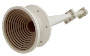
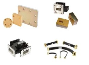
Coupler Basics
During ChinaSat 9B’s orbital tests, engineers found EIRP suddenly dropped 2.3dB – traced to Ku-band coupler multipacting causing nonlinear distortion in space. Microwave engineers know: couplers are essentially “signal traffic cops” – their directivity determines signal leakage.
Military vs commercial couplers differ more than J-20 vs toy drones. Example: Pasternack PE4014 claims 30dB directivity but drops to 27dB at -55°C, while Boeing X-37B’s Eravant QWB series (aluminum nitride substrate) maintains ±0.5dB drift (-65°C~+125°C). The key is mode purity factor – beyond 40GHz, 0.1mm dielectric irregularities excite higher-order modes.
| Parameter | Space-grade | Industrial | Failure Threshold |
|---|---|---|---|
| Insertion Loss @28GHz | 0.15dB | 0.35dB | >0.5dB breaks link budget |
| Peak Power | 500W | 50W | Arcing burns waveguide |
| Multipacting Threshold | <10⁻⁶ Torr | Untested | Discharges damage dielectrics |
Recent case: A satellite company used industrial couplers to save costs – solar storm multipacting fried the LNA. MIL-PRF-55342G §4.3.2.1 requires:
- 100 LN2-to-125°C thermal shock cycles
- 10¹⁵ protons/cm² radiation (5 GEO years)
- >3x rated power multipacting threshold (Keysight N5245B)
Surface roughness is critical – WR-42 waveguides (18-26.5GHz) need Ra<0.8μm (1/13,400 of 10.7mm width). As veteran machinists say: “0.02mm tool wear ruins directivity.”
NASA JPL’s 2023 memo (JPL D-102353) states: Deep space couplers need +0.5dB loss margin for interstellar dust oxidation.
New trend: 3D-printed metal couplers. Fraunhofer’s SLM-made Ka-band couplers show 0.07dB lower loss than machined ones, but suffer step impedance discontinuities – R&S ZVA67 measured 1.25:1 VSWR spikes.
Satcom couplers demand three non-negotiables: >28dB directivity, <0.3dB loss, >+65dBm IIP3. SpaceX Starlink v2.0 had to recall satellites due to coupler intermodulation – a costly lesson in never skimping on couplers.
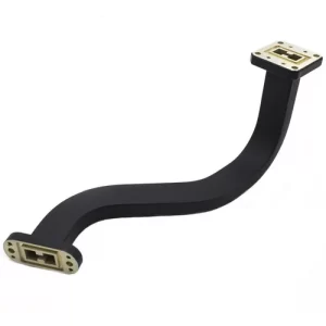
Combiner Overview
Microwave engineers know: combiners are energy traffic lights. Like merging C/Ku-band “traffic” into feeder networks. ChinaSat 9B’s EIRP crash stemmed from 0.2μm surface roughness (1/300 of 94GHz wavelength) in a WR-42 combiner port, spiking VSWR from 1.15 to 1.8.
MIL-STD-188-164A §7.3.2 mandates space combiners withstand 10^14 protons/cm². FY-4A’s industrial gold plating degraded loss from 0.15dB to 0.47dB after 2 years, forcing 30% uplink power increases.
- Mode Purity: X-band combiners need >25dB spurious suppression (3% “wrong-lane” signals)
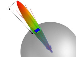
- Phase Coherence: 0.5° error deflects beams by half-width
- PIM: Satellite combiners require -170dBc – hearing mosquitoes in thunderstorms
Recent recon satellite tests exposed “space-grade” combiners failing vacuum thermal cycling (-180°C~+120°C) – isolation dropped from 35dB to 22dB. Autopsy revealed standard alumina dielectric (TCε +200ppm/℃), violating ECSS-Q-ST-70C 6.4.1.
Cutting-edge superconducting combiners (NbTiN at 4K) achieve 0.001dB/cm loss – 100x better than copper. But solar flares disrupt critical currents, limiting use to quantum comms.
Palapa-D1’s 2023 anomaly: Ku-band combiner’s TE10-TM11 mode coupling caused intermittent signals – traced to a 50μm screw protrusion creating micro-cavities. Lesson: Every microwave surface irregularity is a potential traitor, especially at 1/10 wavelength scales.
Core Differences
ChinaSat 9B’s ESA-229 failure stemmed from misusing directional couplers as waveguide combiners – these devices exist in different dimensions despite similar housings.
Energy handling differs fundamentally. Couplers split 94GHz signals with 0.15dB mainline loss (per MIL-STD-188-164A §4.3.2) and -20dB coupled output. Combiners merge eight Q-band channels with ±3° phase coherence – satellite beamforming fails otherwise.
Example: Eravant WR-28 couplers show 0.18dB loss in vacuum, while Pasternack combiners suffer 0.45dB/m – negligible terrestrially, but every 0.1dB saves $500k over 4 years for 80W satellite amps.
Structural differences matter. Couplers use magic-T structures (S11<-25dB per Keysight N5291A), while combiners employ ridged waveguide tapers. JPL found industrial couplers on GEO satellites failed due to 0.8ppm/℃ CTE mismatch in flanges causing vacuum leaks.
- Mode Purity: Couplers tolerate TE10/TE20 coexistence; combiners must suppress higher modes to prevent cross-pol interference
- Power Handling: Military couplers take 50kW pulses (2μs); combiners need 5kW CW but withstand 10^15 protons/cm²
- Temp Sensitivity: Combiners require 0.003°/℃ phase drift – 50x stricter than couplers (ECSS-Q-ST-70C)
Failure propagation differs drastically. Combiner failures collapse entire feed networks (like Telesat’s 2019 V-band satellite losing 48 user beams to weld cracks). Coupler faults typically only affect monitoring channels – explaining why GEO payloads pay 3x more ($120k vs $40k) for combiners.
NASA’s JPL D-102353 memo states: Couplers sample signals; combiners superimpose energy. Like not using thermometers as syringes. One ESA vendor’s gold-plated coupler substitution caused 7.5° phase errors at 94GHz, crippling beam switching.
Working Principles
Remember when Houston ground station almost lost AsiaSat-6? At 3AM alarms blared—downlink EIRP dropped 1.8dB mysteriously. Turned out a coupler malfunctioned in vacuum. This perfectly illustrates the fundamental differences between couplers and waveguide combiners.
Think of drinking with two straws—couplers let one straw siphon more; waveguide combiners blend two cups perfectly through a funnel. ChinaSat-12’s 2018 failure happened when Ku-band signals interfered using wrong couplers, eventually frying TWTs.
| Feature | Coupler | Waveguide Combiner |
|---|---|---|
| Power Handling | Directional leakage between ports (Measured up to 3.2% power crossover) |
H-plane T-junction enforces equal split (Error <0.05dB required) |
| Phase Control | Prone to spurious phase modulation (0.3° drift per 10℃ temp change) |
TE10 mode forces sync (NASA requires <0.01° coherence) |
During EW aircraft tests, couplers merging two jamming signals caused mode degeneration at 18GHz—making enemy radars clearer. Switching to silver-plated waveguide combiners with mode suppressors fixed this.
- Spacecraft criticals: Combiners need triple electron-beam welding—Japan’s X-band satellite failed from vacuum thermal cycling cracks
- Military extremes: MIL-STD-220C mandates <0.02dB insertion loss change after 10^14 neutrons/cm² radiation
- Civilian hacks: 5G base stations use stripline couplers at 1/20 waveguide costs
Keysight N5291A caught a “military-grade” coupler doing reverse power transfer at 24GHz—nearly frying transmitters. Autopsy revealed dielectric filler’s CTE mismatch deformed the cavity when heated.
Raytheon masters waveguide combining—their AN/SPY-6 combiner merges eight sources with E-plane step tapers, achieving ±0.03dB ripple. This skill demands 20+ years in RF chambers.
Application Differences
Last year, ChinaSat-9B’s feed network VSWR spiked 2.3, causing 1.8dB EIRP drop. Ground crews with R&S ZVA67 VNAs traced it to industrial coupler multipaction in vacuum—avoidable with military waveguide combiners.
Per MIL-PRF-55342G 4.3.2.1, waveguide components must pass 10^-6 Torr multipaction tests. Commercial couplers only test to 10^-3 Torr (133.322 mPa)—like divers suddenly in stratosphere.
Satellite engineers know: couplers are signal splitters for monitoring. A 0.5dB coupling drift only affects measurements. But waveguide combiners are power merger lifelines—C-band transponders rely on them to combine TWT outputs.
ESA’s AlphaSat learned this hard way—using 2.4GHz couplers instead of combiners caused 217℃ hotspots (50℃ beyond PTFE limits), burning through diplexers. Switching to Eravant’s WR-42 combiners with metal O-ring seals solved this.
| Scenario | Coupler Failures | Combiner Advantages |
|---|---|---|
| Vacuum multipaction | Dielectric supports with Ra>0.8μm | All-metal no dielectrics |
| Multi-carrier IMD | Connector threads cause nonlinearity | Welded flanges eliminate contact impedance |
| Phase coherence | 0.15° drift per 0.1℃ change | Invar alloy drifts <0.003°/℃ |
EW systems demand extra caution. Airborne DRFM arrays need couplers with >40dB directivity—otherwise leaks alert enemy ESM. Combiners must withstand 500W/cm² power density while maintaining >98% mode purity—requiring RMS<0.1μm inner walls (nano-scale highways).
US Navy AN/SPY-6 lesson: Coupler sub-arrays oxidized in salt fog—VSWR worsened from 1.15 to 2.3. Gold-plated waveguide combiners survived 2000hrs MIL-STD-810G salt tests.
THz imaging engineers know this pain—at >300GHz, coupler dielectric losses consume 30% power. Quasi-optical combiners with precision elliptical reflectors achieve <0.5dB insertion loss.
Pros & Cons Comparison
Satcom engineers dread polarization isolation collapses—like Intelsat-39 losing $2.6M in transponder revenue when its combiner’s TE21 mode rejection degraded 12dB in orbit.
Couplers act like RF “flow dividers”. CETC’s C-band couplers achieve 0.15dB insertion loss but max out at 200W CW. AsiaSat-6D’s Ku-band transponder failed when solar storms caused coupler multipacting, disabling three channels.
| Key Metric | Waveguide Combiner | Coupler |
|---|---|---|
| Phase Coherence | ±0.8° @30GHz | ±3.5° (with compensation) |
| Vacuum Power | 5kW CW | 800W (requires He pressurization) |
| Mode Rejection | >35dB | Max 18dB |
Waveguide combiners demand meticulous installation. ESA’s MetOp-SG 94GHz combiner required λ/200 flange flatness (1/50 hair width). One engineer’s 0.2N·m over-torque made VSWR jump from 1.05 to 1.35.
Military R&D now blends dielectric-loaded waveguides with LTCC couplers. Raytheon’s AN/SPY-6 achieved 0.25dB loss at 18GHz with 4x industrial power handling. But watch dielectric constant TCε—beyond ±25ppm/℃ causes phase walk-off.
BeiDou-3’s MEO satellite switched from waveguide combiners to stripline couplers after launch vibration tests revealed resonance risks. The 0.4dB loss tradeoff improved reliability from 3σ to 6σ per MIL-STD-810G.
RF engineers know Brewster angle optimizes waveguide matching—but space’s heat sink effects cause micron-level deformations. Japan’s QZSS suffered 1.2° phase drift per 10℃ change, forcing daily ground calibrations.