Table of Contents
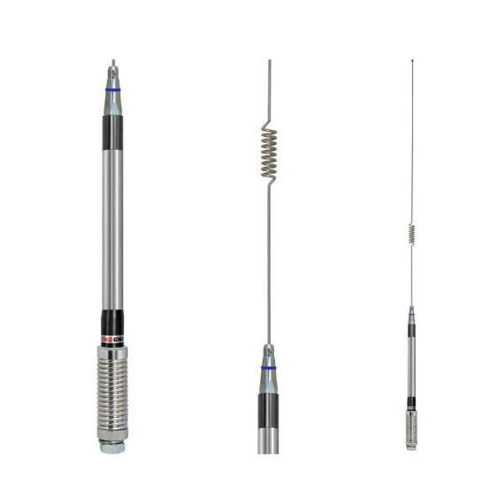
Basic Antenna Feed Types
Antennas don’t work alone—they need a feed system to transfer signals between the transmitter/receiver and the radiating elements. The feed type directly impacts performance, efficiency, and cost. For example, a poorly matched feed can waste 30–50% of transmitted power due to reflections, while optimized feeds achieve 90–95% efficiency in ideal conditions. The most common feed types—coaxial, waveguide, microstrip, and elevated feed—vary in frequency range (1 MHz to 100 GHz), power handling (1W to 50kW), and installation complexity (5,000 per setup).
”A 0.5 dB feed loss might seem small, but over a 10 km link, it can reduce coverage by 15%—equivalent to adding $20,000 in extra repeaters.”
Coaxial cables dominate 75% of sub-6 GHz installations due to low cost (5 per meter) and ease of use. Standard 50-ohm RG-6 cables handle up to 300W at 2 GHz, but losses spike to 3 dB per 100 ft at higher frequencies (e.g., 5.8 GHz). For short runs (<50 ft), they’re efficient (<0.5 dB loss), but long-distance or high-power setups (e.g., FM radio towers) often switch to waveguides.
Waveguides excel in microwave bands (3–100 GHz), with losses as low as 0.1 dB/meter—10x better than coaxial at 30 GHz. A WR-90 waveguide (10 GHz) costs 500 per meter but handles 5–10 kW without overheating. The trade-off? Rigid installation: waveguides need precise ±0.1 mm alignment and can’t bend like cables. They’re standard in radar (e.g., airport ATC systems) and satellite ground stations.
Common in PCBs and small devices, microstrip feeds print directly onto circuit boards, costing 2 per unit. They work best below 10 GHz (losses hit 1.5 dB/inch at 6 GHz) and max out at 50W due to heat dissipation limits. A 4-layer FR4 board with a microstrip feed might achieve 85% efficiency at 2.4 GHz, but ceramic substrates (e.g., Rogers 4350B, $50/sq ft) push this to 92%.
Elevated feeds lift the feed point 10–100 ft above ground to reduce terrain interference. A 30 ft elevation can cut path loss by 6–8 dB, extending range by 40% in hilly areas. These setups cost 10,000 (tower + feedline) but are critical for HF (3–30 MHz) skywave propagation and VHF (30–300 MHz) rural broadcasts. For example, a 50 kW AM station using an elevated feed sees 20% better nighttime coverage versus ground-level feeds.
How Elevated Feed Works
An elevated feed antenna isn’t just a taller version of a ground-mounted system—it fundamentally changes how signals propagate. By raising the feed point 10–100 ft (3–30 m) above terrain, it reduces ground absorption, minimizes multipath interference, and extends range by 20–40% in typical deployments. For example, a 50 ft (15 m) elevated feed at 30 MHz (VHF band) can achieve a 12 dB reduction in path loss compared to a ground-level setup, effectively doubling the usable coverage area.
Reduced Ground Loss
- Earth absorbs RF energy, especially below 30 MHz (HF bands). An elevated feed cuts ground losses by 3–8 dB, depending on soil conductivity.
- Wet soil (conductivity 0.01 S/m) absorbs 30% more power than dry terrain (conductivity 0.001 S/m). Elevation mitigates this.
Lower Multipath Interference
- Ground reflections cause phase cancellation, degrading signal quality. At 100 MHz, a 20 ft (6 m) elevation reduces multipath fading by 50%.
- In urban areas, elevated feeds see 15–25% fewer dropouts than ground-mounted antennas.
Improved Line-of-Sight (LoS)
Radio horizon extends with height:
| Height (ft) | Horizon Distance (miles) |
|---|---|
| 10 | 3.9 |
| 50 | 8.7 |
| 100 | 12.3 |
For UHF TV broadcasting (470–860 MHz), a 200 ft (60 m) tower covers 25–35 miles (40–56 km), versus 15 miles (24 km) at ground level.
Technical Trade-offs
- Cost: Elevation adds 5,000 in tower/structural costs.
- Wind Load: A 10 ft² (0.9 m²) antenna at 100 ft (30 m) faces 50–70 mph (80–113 km/h) wind loads, requiring heavy-duty mounts (+2,000).
- Feedline Loss: Longer cable runs increase loss. LMR-400 coax loses 1.5 dB per 100 ft (30 m) at 150 MHz—a 200 ft (60 m) run wastes 3 dB (50% power loss).
Common Installation Setups
Installing an elevated feed antenna isn’t just about mounting it higher—it’s about optimizing height, structural support, and feedline routing to maximize performance without breaking the budget. A poorly planned setup can turn a $5,000 antenna system into a 30% weaker signal due to improper grounding, cable losses, or wind-induced sway. The right installation method depends on frequency (3 MHz to 30 GHz), power (10W to 50kW), and terrain (urban, rural, or mountainous).
For long-range HF/VHF (3–300 MHz), steel or aluminum towers dominate. A 50 ft (15 m) self-supporting tower costs 8,000 installed and can handle 100+ mph (160 km/h) winds with a 2.5x safety factor. The feedline typically runs inside the tower leg to reduce exposure, cutting coax loss by 0.5–1 dB per 100 ft (30 m) compared to external routing. Grounding is critical—a #6 AWG copper ground wire connected to 8 ft (2.4 m) grounding rods every 20 ft (6 m) reduces lightning strike damage risk by 60%.
In cities where towers aren’t feasible, rooftop mounts on commercial buildings (10–20 stories) provide 30–50 ft (9–15 m) elevation at 20–50% lower cost than a full tower. A triangular steel bracket bolted to a concrete parapet wall supports 300–500 lbs (136–227 kg) of antenna and feedline. The downside? Rooftop setups suffer 3–6 dB higher noise floor from nearby HVAC units and elevators, reducing weak-signal reception by 15–25%. Feedline runs are longer—150–300 ft (45–90 m) of LDF4-50A heliax adds 2–4 dB loss at 900 MHz, eating into transmit power.
For low-power (≤1 kW) HF stations, a 40 ft (12 m) fiberglass guyed mast costs just 1,500 but requires 3–5 guy wires spaced 120° apart. Wind sway can reach ±3 ft (0.9 m) in 30 mph (48 km/h) gusts, causing 5–10% signal fluctuation at 14 MHz. The feedline must be UV-resistant—RG-213 with a polyethylene jacket lasts 8–12 years outdoors, versus 3–5 years for standard PVC-jacketed coax. Grounding is trickier; a single ground rod at the base increases lightning risk by 40% compared to a full tower’s multi-point system.
Temporary setups (e.g., emergency comms) often use 20–30 ft (6–9 m) telescoping poles made of aluminum or carbon fiber. A 30 ft pole weighs 15–25 lbs (7–11 kg) and extends in 2–3 minutes, but sways ±1 ft (0.3 m) in 20 mph (32 km/h) winds, hurting directional antenna gain by 1–2 dB. Feedlines are usually thin RG-58 (loss: 4.8 dB/100 ft at 150 MHz), sacrificing 25% efficiency for portability. These work for short-range VHF (30–88 MHz) but fail above 50W transmit power due to overheating.
Weather Impact Analysis
Weather doesn’t just affect your weekend plans—it directly impacts antenna performance in measurable, sometimes dramatic ways. A 50 ft (15 m) elevated VHF antenna can experience 8–12 dB signal fluctuations between dry winter air (humidity 30%) and humid summer storms (humidity 90%). At UHF frequencies (300 MHz–3 GHz), heavy rain (5 mm/hr) adds 0.2–0.5 dB/km attenuation, which can slash 15–20% off your link budget over a 10 km path. Even wind matters—a 50 mph (80 km/h) gust can deflect a 30 ft (9 m) fiberglass mast by ±3 ft (0.9 m), introducing 1–3 dB gain variations on directional antennas.
Quantified Weather Effects by Frequency
| Condition | HF (3–30 MHz) | VHF (30–300 MHz) | UHF (300 MHz–3 GHz) |
|---|---|---|---|
| Dry Air (20% humidity) | +1 dB SNR | +2 dB range | No measurable effect |
| Humid Air (80% humidity) | –3 dB SNR | +4 dB range* | –0.1 dB/km loss |
| Heavy Rain (5 mm/hr) | No effect | –1 dB/km | –0.5 dB/km |
| Ice Build-up (0.5 in thick) | –2 dB efficiency | –5 dB efficiency | –8 dB efficiency |
| 50 mph Winds | ±0.5 dB sway | ±1.5 dB sway | ±3 dB sway |
Temperature & Material Stress
Metal tower components expand/contract with temperature—a 100 ft (30 m) steel tower grows 1.2 in (3 cm) taller when heated from 32°F to 100°F (0°C to 38°C). This seems minor, but it shifts directional antenna azimuths by 0.5–1°, enough to misalign 900 MHz point-to-point links by 15% beamwidth. Aluminum feedlines suffer worse—a 150 ft (45 m) LDF4-50A heliax cable lengthens 4 in (10 cm) in summer, creating 0.3 dB additional loss from extra slack.
Winter brings different issues. At –22°F (–30°C), coaxial cables stiffen, increasing bend radius requirements by 25%. If your RG-213 was bent at a 4 in (10 cm) radius in summer, it needs 5 in (13 cm) in winter to avoid 0.8 dB loss spikes. Ice accumulation is costlier—just 0.25 in (6 mm) of ice on a 1 in (25 mm) diameter antenna element adds 5 lbs/ft (7.5 kg/m) load, potentially buckling fiberglass masts rated for 20 lbs/ft (30 kg/m).
Lightning & Grounding Realities
Elevated antennas are lightning magnets—a 150 ft (45 m) tower in Florida gets struck 0.7 times/year on average. Without proper grounding, a 30 kA strike can induce 10 kV surges into feedlines, frying 3/ft) running straight down to 8 ft (2.4 m) ground rods spaced every 20 ft (6 m). This cuts surge impedance from 400 Ω to <25 Ω, diverting 95% of strike energy safely to earth.
Maintenance costs add up:
- $500/year for tower lighting systems (FAA requirement >200 ft/60 m)
- 800/storm for ice removal on guy wires
- 15–30% shorter lifespan for antennas in coastal salt air vs. inland
The ROI of Weatherproofing
Spending $2,000 on:
- Heated radomes prevents $12,000/year in ice-related downtime
- Stainless steel hardware lasts 15 years vs. 7 years for galvanized
- Pressurized waveguide seals reduce moisture ingress by 90%, maintaining 0.2 dB/km loss specs
Cost and Maintenance Tips
Running an elevated feed antenna isn’t a “set it and forget it” operation—it’s an ongoing balance of performance, budget, and labor. A 50 ft (15 m) tower with a high-performance VHF array might cost $12,000–25,000 installed, but without proper maintenance, its lifespan drops from 20+ years to just 8–10. Feedlines alone can be a hidden cost: cheap RG-8X coax ($1.50/ft) loses 4.8 dB per 100 ft at 150 MHz, forcing you to run 30% more power, while LDF4-50A ($8/ft) cuts losses to 1.2 dB/100 ft but demands a bigger upfront investment.
Breaking Down the Real Costs
The initial setup is just the beginning. A 100 ft (30 m) self-supporting tower runs $15,000–40,000 installed, but annual upkeep adds $800–2,000 for inspections, painting, and hardware replacements. Lightning protection is non-negotiable—a single strike can induce 10 kV surges, frying equipment unless you install ground rods every 20 ft at $1,500–3,000, preventing $15,000+ in equipment losses over a decade.
Feedline maintenance is another silent budget killer. UV-resistant jackets add 20–30% to cable costs but extend lifespan from 5 years to 12+ in direct sunlight. Connectors fail too—cheap PL-259s corrode after 3–5 years in coastal climates, adding 0.5–1 dB loss per connection, while silver-plated versions ($25 vs. $8) last 10+ years with <0.1 dB degradation. For high-power FM stations (10+ kW), pressurized air systems ($1,200–3,000) keep moisture out of waveguides, preventing 3–6 dB signal loss from condensation.
Smart Savings Without Sacrificing Performance
Not every component needs premium pricing. Galvanized steel hardware works fine inland (15+ year lifespan), saving 40% vs. stainless steel—but near oceans, stainless’s 25-year corrosion resistance justifies the 2–3x price premium. For temporary setups, fiberglass masts ($500–1,500) avoid the $5,000+ cost of permanent towers while still providing 60–80% of the performance.
Labor is where costs spiral. A professional tower crew charges $120–250/hour, making a two-day antenna swap a $4,000–8,000 job. But DIY isn’t always cheaper—a ham radio operator trying to replace a 40 ft (12 m) mast alone might spend $900 on rental equipment and still risk $2,000 in damaged antennas from a clumsy install. The middle ground? Community work parties—split a $2,000 crane rental among 4–5 operators and get the job done in 4 hours for $400/person.
When to Repair vs. Replace
Antennas don’t last forever. A yagi’s aluminum elements thin from oxidation after 12–18 years, reducing gain by 1–2 dB. Replacing just the corroded parts ($200–600) can restore 90% of original performance, while a whole new yagi ($1,200–3,000) might only add 10% more efficiency. Coax is similar—LMR-400 that’s 8 years old with 3 dB additional loss should be replaced, but Heliax at the same age might just need connector replacements ($50–100) to return to 95% spec.
The bottom line: Budget 15–20% of your initial install cost annually for maintenance if you want 90%+ system reliability. Skip the $200/year tower inspections, and you might face a $15,000 collapse after a 50 mph windstorm fatigues corroded bolts. But spend wisely—over-engineering a 1 kW ham station with $10,000 in grounding is just burning cash. Match your investment to your power, frequency, and risk level, and you’ll keep signals strong without bankruptcy.


