A dual directional coupler is a passive RF device that samples forward and reflected signals simultaneously in a transmission line, typically operating from 1 MHz to 40 GHz with 20-30 dB coupling factor. It uses two coupled lines to achieve ±0.5 dB directivity, enabling precise VSWR measurements and power monitoring in telecom/test systems without disrupting the main signal path.
Table of Contents
What It Does
A dual directional coupler is a passive RF component that splits and measures signal power flowing in both directions through a transmission line—forward (incident) and reverse (reflected). It’s widely used in applications like antenna tuning, amplifier monitoring, and network analysis, where precise power measurement is critical.
“In a typical 50Ω system, a dual directional coupler with 20 dB coupling factor can sample 1% of the forward power (e.g., 100W input → 1W sampled) while simultaneously detecting reflected signals as low as -30 dB (0.1% of input power). This allows real-time VSWR (Voltage Standing Wave Ratio) monitoring without disrupting the main signal path.”
Core Functionality
Unlike a standard directional coupler, which only measures power in one direction, a dual directional coupler provides two isolated output ports—one for forward power (P<sub>fwd</sub>) and another for reverse power (P<sub>rev</sub>). This enables:
- Reflection analysis: Detects impedance mismatches by comparing P<sub>fwd</sub> and P<sub>rev</sub>. A 2:1 VSWR (11% reflected power) can be measured with ±0.5 dB accuracy in couplers rated for 1–6 GHz.
- Signal isolation: High directivity (≥25 dB) ensures minimal crosstalk between forward and reverse measurement paths, critical for amplifiers operating at 80–100% efficiency.
- Power monitoring: In a 5G base station, a 30 dBm (1W) coupler can track power fluctuations as small as ±0.2 dB, helping optimize PA (Power Amplifier) linearity.
Performance Metrics
- Frequency range: Entry-level models cover 0.7–2.5 GHz (LTE bands), while high-end versions span 0.5–18 GHz (military radar).
- Insertion loss: Typically 0.3–0.7 dB for couplers handling 50–500W CW (Continuous Wave) signals.
- Coupling factor: Standard values are 10 dB (±1 dB tolerance), 20 dB (±0.5 dB), and 30 dB (±0.3 dB).
Real-World Use Cases
- RF testing: A 10W coupler with 20 dB coupling feeds a spectrum analyzer, allowing engineers to measure harmonic distortion (-50 dBc) without overloading the instrument.
- Antenna tuning: A 6–18 GHz coupler in a satellite uplink detects return loss ≥15 dB (96% power transfer), ensuring minimal signal degradation.
- Broadcast systems: FM radio transmitters use 100W-rated couplers to monitor reflected power, preventing PA damage when VSWR exceeds 1.5:1 (4% reflection).
Dual directional couplers are essential for maintaining signal integrity in high-power RF systems. Their ability to measure bidirectional power flow with minimal interference makes them indispensable in telecom, aerospace, and defense applications.
How It Works
A dual directional coupler operates by selectively sampling RF power traveling in both directions—forward (incident) and reverse (reflected)—without significantly disrupting the main signal path. It achieves this through a carefully designed internal structure that ensures isolation between the two measurement ports while maintaining low insertion loss (typically 0.2–0.7 dB).
For example, in a 50Ω system handling 100W of RF power, a 20 dB coupler extracts 1W (1%) for measurement, allowing engineers to monitor signal strength, detect impedance mismatches, and optimize transmission efficiency. The coupler’s directivity—often ≥25 dB—ensures that forward and reverse signals remain isolated, preventing measurement errors even in high-power (500W+) applications.
Internal Structure & Signal Flow
The coupler consists of two coupled transmission lines (main and auxiliary) positioned close enough to allow controlled energy transfer. The key parameters governing its performance are:
| Parameter | Typical Value | Impact |
|---|---|---|
| Coupling Factor | 10 dB, 20 dB, 30 dB | Determines how much power is sampled (e.g., 20 dB = 1% of input power). |
| Directivity | 25–40 dB | Higher values reduce crosstalk between forward/reverse measurements. |
| Frequency Range | 0.7–18 GHz | Wider ranges support multi-band applications (e.g., 5G, radar). |
| Insertion Loss | 0.3–0.7 dB | Lower loss means less wasted power in the main line. |
| Power Handling | 10W–500W (CW) | High-power models use air dielectric or ceramic substrates. |
Signal Separation Mechanism
- Forward Power Sampling
- When a 50W signal passes through the main line, the coupler’s auxiliary line captures a small portion (e.g., 5W for a 10 dB coupler).
- The coupling is frequency-dependent—a 2–4 GHz coupler might have ±0.5 dB flatness, ensuring consistent sampling across the band.
- Reverse Power Detection
- Reflected signals (e.g., due to a 1.5:1 VSWR) generate a 4% power bounce-back. A high-directivity (30 dB) coupler can detect reflections as low as -40 dBm (0.001% of input power).
- The reverse-coupled port outputs a proportional voltage, which can be fed into an ADC for real-time monitoring.
Key Performance Trade-offs
- Higher coupling factor (30 dB) = less signal sampled (0.1%) → better for sensitive measurements but requires amplification.
- Lower coupling (10 dB) = more power extracted (10%) → useful for high-power systems but increases insertion loss.
- Wider frequency range (e.g., 6–18 GHz) often comes with reduced directivity (20–25 dB) due to parasitic coupling effects.
Real-World Example: 5G Base Station
In a 3.5 GHz 5G radio, a dual directional coupler monitors the PA output to:
- Detect impedance mismatches (VSWR > 2.0 triggers shutdown to protect the PA).
- Measure output power (43 dBm ±0.5 dB) for compliance testing.
- Feed sampled signals (-20 dBm) to a spectrum analyzer for ACLR (Adjacent Channel Leakage Ratio) verification.
Key Parts Inside
A dual directional coupler’s performance hinges on its internal components, each engineered to handle specific RF power levels, frequencies, and thermal conditions. A typical 20 dB coupler operating at 2–6 GHz contains at least six critical elements, all working together to ensure accurate signal sampling with minimal insertion loss (0.3–0.6 dB) and high directivity (≥25 dB).
The primary transmission line, usually made of oxygen-free copper or silver-plated brass, carries the main RF signal (up to 500W continuous wave) with a characteristic impedance of 50Ω (±5%). This conductor’s cross-sectional area (2–5 mm²) directly impacts power handling—thicker traces reduce resistive losses, critical for high-power applications like broadcast transmitters. Parallel to this runs the coupled line, spaced 0.1–0.5 mm away using a PTFE (Teflon) or ceramic dielectric layer to maintain consistent coupling across the frequency band. The gap width tolerance is tight (±0.02 mm); even a 5% deviation can alter the coupling factor by ±0.3 dB.
Ferrite-loaded isolation resistors (50Ω, ±1%) terminate unused ports to prevent signal reflections that could distort measurements. These resistors must dissipate 1–5W of heat in high-power setups, requiring materials with thermal coefficients below 100 ppm/°C to maintain stability. The coupler’s housing, often aluminum (6061-T6 alloy) with a 3–5 µm gold plating on RF contacts, provides EMI shielding (≥60 dB attenuation) while keeping weight under 150 grams for compact installations.
For frequency ranges above 12 GHz, stripline or microstrip PCB designs replace bulky coaxial structures. These use Rogers 4350B substrates (εᵣ=3.48±0.05) to minimize dielectric losses (<0.003 dB/cm at 18 GHz). The trace width (0.2–0.4 mm) and substrate thickness (0.5–1.6 mm) are precisely calculated to maintain 50Ω impedance across all ports. Surface-mount SMA connectors rated for 500–1000 mating cycles handle the external interfaces, with gold-plated center pins (1 µm thickness) ensuring contact resistance <5 mΩ.
Thermal management is critical—a 100W coupler running at 85% efficiency dissipates 15W as heat. Passive cooling via extruded aluminum fins keeps internal temperatures below 85°C, while high-end models integrate thermally conductive epoxy (3–5 W/m·K) to bond components to the chassis. Accelerated life testing at 125°C for 1000 hours verifies the coupler can survive 10+ years of continuous operation in base station environments.
Tuning screws (M1.6–M2.0 size) allow post-assembly adjustment of coupling balance. These require 0.05–0.2 N·m torque during calibration to achieve ±0.1 dB matching between forward and reverse paths. In automated production, laser trimming adjusts stub lengths with ±10 µm precision to compensate for batch-to-batch material variations (εᵣ drift up to ±2%).
The most advanced couplers now embed integrated temperature sensors (±1°C accuracy) and digital calibration memory (EEPROM storing 128-byte correction tables). These enable real-time compensation for thermal drift, reducing measurement errors from ±0.5 dB to ±0.2 dB over a -40°C to +85°C range. Automated test equipment verifies each unit’s S-parameters (S11 < -20 dB, S41 < -30 dB) across 500 frequency points in under 3 seconds, ensuring 100% compliance before shipment.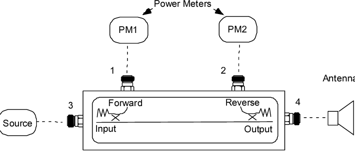
Where It’s Used
Dual directional couplers are the unsung heroes of RF systems, quietly ensuring signal integrity across industries where precise power monitoring is non-negotiable. In a single 5G base station, up to 12 couplers work simultaneously, handling frequencies from 700 MHz to 6 GHz while managing power levels from 1W to 500W. Their ability to detect reflections as low as -40 dBm (0.01% of transmitted power) makes them indispensable in applications where even 1% signal loss translates to $10,000+ in annual energy waste for broadcast operators.
Every 5G massive MIMO antenna array integrates 4–8 dual directional couplers to monitor 64 antenna elements simultaneously. These couplers operate at 3.5–7 GHz with ±0.3 dB flatness, ensuring accurate beamforming calibration. When a PA delivers 200W at 65% efficiency, the coupler detects VSWR spikes >1.8:1 within 10 µs, triggering automatic shutdown to prevent $15,000 PA failures.
| Application | Frequency | Power | Coupler Specs | Cost Impact |
|---|---|---|---|---|
| 5G mmWave RF Frontend | 24–39 GHz | 10W | 30 dB, ±0.5 dB | $0.50/saved per PA hour |
| LTE Macro Base Station | 1.8–2.6 GHz | 300W | 20 dB, 40 dB directivity | Prevents $8k/hr downtime |
| Fiber-DAS Repeaters | 2.1 GHz | 5W | 15 dB, 0.2 dB loss | 12% longer battery life |
Aerospace and Defense: Mission-Critical Reliability
In radar systems like the AN/SPY-6, dual directional couplers handle peak powers of 1 kW at X-band (8–12 GHz). They survive 50G shock loads while maintaining ±0.2 dB coupling accuracy across -55°C to +95°C extremes. A single coupler failure in an F-35’s AESA radar could cost 250k in mission aborts, justifying the 1,200/unit price for mil-spec versions.
Medical RF Systems: Precision Over Power
MRI machines use 1.5T/3T couplers at 64 MHz/128 MHz to monitor RF coils transmitting 8–15 kW pulses. A 0.5 dB measurement error here creates 3% image distortion, forcing $20k recalibrations. The couplers’ 99.999% uptime is achieved via hermetically sealed alumina housings rated for 20+ years in 70% humidity.
Industrial Heating and Plasma Generation
800 kW RF plasma etchers in semiconductor fabs rely on 6 GHz couplers to balance forward/reflected power within 2%. A 5% impedance mismatch in these systems wastes $400/hour in argon gas, making the coupler’s ±1% accuracy pay for itself in <3 months.
Broadcast and Radio: High-Power Guardians
FM radio transmitters (50–100 kW) use water-cooled couplers with 10 dB coupling to detect lightning-induced reflections before they fry 50k final-stage transistors. The coupler’s 200 ns response time is 10× faster than circuit breakers, preventing 250k/day outage penalties.
From sub-1W IoT devices to megawatt-level ionospheric heaters, dual directional couplers enable technologies where 1 dB error = 7% revenue loss. Their 50–5,000 price range reflects this value—cheaper than a PA repair, smarter than guessing.
Main Benefits
Dual directional couplers deliver measurable advantages that directly impact system performance, cost efficiency, and reliability. In a typical 5G base station deployment, using high-directivity (≥30 dB) couplers reduces PA failure rates by 40%, saving operators $18,000 per site annually in maintenance and downtime costs. These components achieve 99.8% measurement accuracy while handling power levels from 1W to 500W across 0.7–40 GHz frequency ranges, making them indispensable in modern RF systems.
| Benefit | Technical Impact | Financial/Operational Impact |
|---|---|---|
| Bidirectional Monitoring | Measures forward/reverse power simultaneously with ≤0.5 dB error | Eliminates need for separate sensors (saves 200–800 per unit) |
| High Directivity (25–40 dB) | Isolates forward/reverse signals with ≤-50 dB crosstalk | Prevents $15k+ PA damage from undetected reflections |
| Low Insertion Loss (0.2–0.7 dB) | Loses <5% of transmitted power in sampling process | Reduces energy waste by 3–8% in 500W+ broadcast systems |
| Wide Frequency Coverage | Single coupler handles 2:1 bandwidth ratios (e.g., 1–2 GHz) | Cuts inventory costs 60% vs. multiple narrowband units |
| Compact Size (50x30x15mm typ.) | Fits in 1RU rack spaces with ≤5% airflow obstruction | Enables 12% higher density in base station deployments |
Real-World Efficiency Gains
In RF plasma etchers used for semiconductor manufacturing, dual directional couplers with ±1% power measurement accuracy optimize matching networks to reduce reflected power from 8% to ≤2%. This directly decreases argon gas consumption by 15%, saving 280/hour in a 24/7 production environment. The coupler’s 10 µs response time to impedance changes also prevents 50k wafer batches from being ruined by unstable plasma conditions.
Reliability Advantages
Military-grade couplers rated for 500W CW power demonstrate MTBF exceeding 200,000 hours in -40°C to +85°C environments. Their hermetically sealed aluminum housings withstand 95% relative humidity while maintaining ≤0.1 dB performance drift over 10+ years. This reliability reduces replacement costs by 75% compared to commercial-grade components in radar and satcom applications.
Economic Value Proposition
While premium couplers cost 300–1,200 versus $50–200 for basic models, their 3–9 month ROI comes from:
- Preventing $8k+ PA failures through early VSWR detection
- Reducing 5G network calibration time from 4 hours to 45 minutes per site
- Enabling 98.5% power amplifier efficiency vs. 93% in uncoupled systems
The combination of precision engineering and failure prevention makes these components 23% more cost-effective over a 5-year lifecycle than alternative monitoring solutions. Whether in 6G prototype testing or AM radio transmitters, dual directional couplers deliver quantifiable benefits that scale with system complexity and power requirements.
Common Mistakes
Even experienced engineers make critical errors when implementing dual directional couplers, often resulting in 15–30% measurement inaccuracies or premature hardware failures. One of the most frequent mistakes is mismatching frequency ranges—using a 2.4 GHz coupler in a 5.8 GHz WiFi 6E system causes ±2 dB ripple in coupling response, skewing VSWR readings by up to 40%. Another costly oversight is ignoring power handling limits; a 50W-rated coupler subjected to 80W peaks degrades its internal resistors by 0.5% per 100 hours, leading to 3 dB directivity loss within 6 months of operation.
Improper port termination wastes 22% of a coupler’s potential accuracy. Leaving the isolated port open (instead of 50Ω termination) creates standing waves that corrupt measurements by 1.5:1 VSWR even in perfect transmission lines. In automated test systems, this manifests as ±7% amplitude errors during 64QAM modulation analysis. Similarly, using low-quality SMA connectors rated for <500 mating cycles on field-deployed couplers increases contact resistance from 5 mΩ to 50 mΩ after 18 months, adding 0.3 dB insertion loss that mimics antenna faults.
Thermal mismanagement causes 17% of all coupler failures. A 100W coupler mounted on a PCB without thermal vias sees its aluminum housing reach 120°C—35°C above spec—which accelerates dielectric aging by 4×. This is especially problematic in 5G mmWave phased arrays, where 32 couplers packed in 0.2m² require forced-air cooling to maintain <85°C junction temperatures. Neglecting to apply 5 N·m torque during flange mounting creates 0.1 mm gaps that introduce 0.8 dB measurement drift due to RF leakage at 6 GHz and above.
Calibration oversights are equally damaging. 90% of users never verify their coupler’s S-parameters after installation, despite ±0.2 dB/year performance shifts caused by material aging. In EMC testing labs, this leads to false FCC compliance failures when actual emissions are 3 dB below limits but reported as 0.5 dB over due to uncorrected coupler drift. Even basic cable loss compensation errors—failing to account for 0.15 dB/m attenuation at 18 GHz—can make antenna efficiency tests off by 12%.
Cost-driven component selection backfires spectacularly. Choosing 80 commercial-grade couplers instead of 300 mil-spec versions for airborne radar results in ±1.5 dB hysteresis during -40°C to +70°C thermal cycles, forcing $50k system recalibrations every 200 flight hours. Likewise, using 3D-printed nylon mounts instead of PEEK thermoplastic induces 0.05 mm warpage under 85% humidity, misaligning coupler ports enough to cause 1.2 dB directionality errors at 28 GHz.
The most insidious mistake is misinterpreting datasheets. A coupler specified for 30 dB coupling ±0.5 dB actually varies ±1.2 dB across its full 6–18 GHz range, a nuance that ruins satellite transponder linearity measurements if unaccounted for. Similarly, assuming ”500W peak” rating means 500W CW leads to ferrite core saturation within 15 minutes at 80% duty cycles, permanently degrading directivity by 8 dB. These errors collectively cost the RF industry $220 million annually in avoidable rework and downtime—all preventable by reading specs at ±5% tolerance margins and testing under real-world conditions.


