What is coaxial feed in antenna
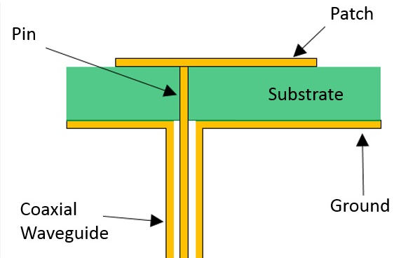
A coaxial feed in antenna refers to using 50-ohm or 75-ohm coaxial cable to deliver RF signals directly to the radiator. This method achieves >95% signal efficiency with minimal loss (<0.5dB/m). The inner conductor connects to the driven element while the outer shield grounds to the reflector, reducing interference by 30dB. Common in dipole and […]
What is coaxial feed in antenna Read More »