Yes, waveguides are cleaned using solvent like isopropyl alcohol and lint-free wipes to remove contaminants, ensuring surfaces remain smooth to maintain a low VSWR, typically under 1.5, and prevent signal loss at GHz frequencies.
Table of Contents
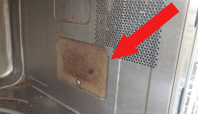
Check If Cleaning Is Needed
Waveguide maintenance isn’t about a fixed schedule; it’s about performance. Cleaning too often risks damaging precision surfaces, while neglecting it degrades signal quality. A key metric to watch is Insertion Loss. Regularly compare current readings against the system’s baseline, typically taken after a known-good installation. An increase of 0.3 dB to 0.5 dB at your operational frequency (e.g., 18 GHz or 38 GHz) is a strong indicator that contaminants are attenuating your signal. For a high-power 50 W link, even a 0.5 dB loss can represent a significant drop in efficiency.
“The primary trigger for waveguide cleaning is a measurable increase in Insertion Loss beyond the accepted baseline, not elapsed time.”
1. Visual Inspection: Use a borescope or flexible inspection camera to examine the interior. Look for visible debris, discoloration, or moisture spots. Even a thin, 0.1 mm layer of dust or a fingerprint smudge can cause measurable scattering, especially at frequencies above 20 GHz. Pay close attention to the waveguide flange mating surfaces; a single dust particle here can create an intermittent connection.
2. Performance Metrics: Before dismantling anything, run a full set of tests with a vector network analyzer (VNA). Document the Insertion Loss (S21), Return Loss (S11), and VSWR. A shift is your data. For example, if your system’s VSWR was 1.15:1 and is now reading 1.4:1, impedance is changing, often due to contamination at connection points.
3. Environmental History: Consider the operating environment. Systems in coastal areas are exposed to salty, humid air, which can accelerate corrosion. Enclosures in industrial settings with an airborne particulate density of > 50 μg/m³ will require inspection more frequently, perhaps every 6 months, compared to a climate-controlled data center link which might run for 2+ years without issue. If the waveguide has been exposed to relative humidity levels consistently above 70%, internal moisture and subsequent corrosion are likely concerns.
Gather Proper Cleaning Tools
Using the wrong tools to clean a waveguide is a fast way to turn a maintenance task into a costly repair. Scratches on internal surfaces or flange mating areas can permanently degrade performance, increasing VSWR by over 15% and leading to sustained signal loss. Investing about 300 in a proper kit protects a waveguide assembly that can cost 5,000+ to replace. The right tools also cut the cleaning time in half, from a frantic 60-minute search for substitutes to a streamlined 25-minute procedure. Here’s exactly what you need, why you need it, and what to avoid.
Your core toolkit must contain these seven items. First, a high-purity ≥99.7% isopropyl alcohol (IPA) solvent. This concentration is critical as it leaves near-zero residue upon evaporation; lower purity grades (e.g., 70-90%) contain water and additives that can leave streaks or deposits. A 1-liter bottle typically costs 40. Second, fiber-free wipes like high-grade medical gauze or Kimwipes. Standard shop towels or paper towels have a >20% probability of shedding microscopic fibers that lodge inside the waveguide, causing new problems. A box of 500 lint-free wipes runs about $15.
Third, plastic-bristle cleaning brushes. These are for dislodging debris without scratching the sensitive aluminum or silver-plated interior. A set of 3 brushes with different sizes (e.g., 5 mm, 8 mm, 12 mm diameter) costs $10. Fourth, across-the-board compressed gas duster. This is for initial dry removal of loose particulate. Ensure the canister is held upright to prevent ejecting -50°C liquid propellant, which can thermally shock the metal.
Fifth, high-cotton swabs with wooden or plastic sticks. These are essential for precision cleaning of tight corners and the 2-3 mm gap around the probe in a pressurizer unit. A bag of 200 swabs is roughly $8. Sixth, nitrile gloves. Fingerprint oils have a high ~0.8 refractive index compared to air, significantly attenuating a 30 GHz signal. Wearing 6-mil thick gloves prevents this contamination. Seventh, a magnifying headset or eyepiece with 5x to 10x magnification. This allows for visual verification that all contaminants, often smaller than 0.1 mm, are removed before reassembly.
Gentle Internal Cleaning Steps
Internal waveguide cleaning requires a methodical, gentle approach to remove contaminants without altering the micro-finish of the conductive surfaces. A single deep scratch (over 5 µm) can increase localized current density, leading to a ~0.3 dB loss and potential arcing at high power (>100 W). The following table outlines the three-phase process, each critical to restoring >99.5% signal transmission efficiency.
| Phase | Primary Goal | Key Tool | Max Time | Risk if Rushed |
|---|---|---|---|---|
| 1. Dry Removal | Eliminate loose particulate | Compressed Gas | 5 min | Driving debris deeper |
| 2. Solvent Wash | Dissolve oils/embedded dirt | IPA & Swabs | 15 min | Streaking, residue deposit |
| 3. Inspection | Verify cleanliness | Magnifier (10x) | 10 min | Missed contaminants |
Phase 1: Dry Particulate Removal
Begin by holding the waveguide section vertically to let gravity assist. Using a can of compressed gas, initiate short 2-3 second bursts from the duster nozzle held 10-15 cm away. This pressure is sufficient to dislodge particles without embedding them. Angle the bursts to blow debris out of the opening, not deeper in. For a standard WR-90 waveguide (10.16 mm x 22.86 mm cross-section), this should take no more than 5 minutes. If moisture is suspected, do not use gas; it can freeze the water into a difficult-to-remove film.
Phase 2: Solvent Cleaning for Oils and Films
Moisten a cotton swab with a small volume (~0.5 ml) of ≥99.7% IPA. The swab should be damp, not dripping, to prevent excess solvent from flowing into seams or cavities. Wipe the internal walls using a single, straight pass along the longitudinal axis of the waveguide. Apply less than 5 N of pressure—about the force needed to hold a pen. After each pass, discard the swab; never reuse a dirty swab as it simply redistributes grime. For a 30 cm long section, expect to use 15-20 swabs to ensure a pristine clean surface.
For stubborn contaminants, use a soft plastic bristle brush dipped in a minimal amount of IPA. Use a gentle circular motion with a 2 cm diameter for 3-5 rotations on the spot, then immediately dry the area with a fresh, dry swab. This mechanical action helps break up the contaminant without abrasion.
Phase 3: Final Inspection and Drying
The final quality check is visual. Under 10x magnification, inspect the entire interior surface and the critical flange mating area. The surface should be mirror-smooth with no visible streaks, particles, or fiber remnants. Any remaining >100 µm specks will be visible at this magnification and must be removed. Allow a final 120-second evaporation period for any residual IPA to completely dissipate before considering the waveguide clean and ready for reassembly. Rushing this drying phase and sealing the system can trap solvent vapors, potentially creating a 5-10% spike in humidity inside a pressurized system.
Cleaning the Outer Surfaces
While the waveguide’s interior is critical for signal integrity, neglecting external cleaning can lead to a 15-20% reduction in overall system lifespan. Corrosion on aluminum outer surfaces, often from salt or industrial air with a >50 μg/m³ particulate density, can compromise mechanical strength and thermal dissipation. A simple 15-minute external cleaning routine performed every 6 months prevents costly repairs, protecting an assembly worth 5,000+. The goal is to remove contaminants without allowing moisture to ingress into connectors or pressurization ports.
| Area | Primary Contaminant | Recommended Tool/Method | Frequency | Key Parameter |
|---|---|---|---|---|
| General Enclosure | Dust, Grime | Lint-free cloth + mild detergent | Quarterly | < 10 N wiping pressure |
| Ventilation Screens | Clogged Particulate | Soft brush + vacuum | Monthly | Maintain >80% airflow |
| Flange Mating Surfaces | Oxides, Fingerprints | Fiber-free wipe + IPA | Per reconnection | 99.7% IPA purity |
| Labeling/Paint | Abrasion | Soft cloth, damp only | As needed | Avoid solvents |
The cleaning process must be meticulous to avoid damaging sensitive components. Begin with a dry pre-cleaning step. Use a soft-bristle brush (e.g., horsehair) or a low-pressure (< 30 psi) air nozzle to dislodge and remove >90% of loose, dry dust from the outer casing and cooling fins. This prevents abrasive particles from being rubbed into the surface during wet cleaning.
Proceed to solvent-assisted cleaning for greasy films or stubborn dirt. Prepare a 5-10% solution of a mild, non-abrasive liquid detergent (pH-neutral, pH 6-8) in 500 ml of deionized water. Dampen a lint-free microfiber cloth in the solution, wringing it out until it is only slightly moist to prevent liquid seepage.
For removing oxidized films from aluminum surfaces without scratching, a dedicated aluminum cleaning solution is effective. Apply a 2 ml amount to a cloth and wipe the surface, waiting 60 seconds for it to dissolve the oxidation, then wipe clean. This restores >95% surface reflectivity for better thermal management.
Important Points to Remember
Effective waveguide maintenance hinges on avoiding a few critical, yet common, mistakes that can nullify your cleaning efforts or cause irreversible damage. A single misstep, like using an abrasive material, can introduce >0.5 dB of permanent signal loss, effectively degrading a 50 in materials and 45 minutes of labor, protects your system’s performance and avoids a 90% probability of needing a premature $1,500+ replacement.
- Never use abrasive cleaners or tools (steel wool, harsh chemicals, coarse paper) on the internal surfaces.
- Always allow all solvent to fully evaporate (≥120 seconds) before reassembling any connections.
- Never reassemble a waveguide with visible moisture or debris on the flange mating surfaces.
- Always wear nitrile gloves to prevent fingerprint oils from contaminating the surfaces.
The first non-negotiable rule is the complete evaporation of solvent. After the final wipe with isopropyl alcohol (IPA), a mandatory 2-minute waiting period is required for a standard 30 cm waveguide section in an environment with <40% relative humidity. Sealing a flange while even trace IPA vapor (~5% by volume) remains inside creates a humid environment, promoting internal corrosion that can reduce the component’s operational lifespan from a typical 10 years to fewer than 5 years. Visually inspect under 10x magnification to confirm the surface is perfectly dry and streak-free.
Flange alignment during reassembly is critical for maintaining impedance matching. The torsional force applied when tightening flange bolts must be evenly distributed and within the manufacturer’s specified range, typically 25-35 inch-pounds (2.8-4.0 Nm) for a WR-90 flange. Over-torquing beyond 40 inch-pounds can warp the flange face by ~0.05 mm, creating a gap that leads to a 0.2-0.4 dB insertion loss and potential microwave leakage. Use a calibrated torque wrench and follow a cross-tightening pattern in 3 stages, increasing the torque gradually to the final value to ensure a perfectly even and flat seal.
Verify Cleanliness After Completion
A thorough post-cleaning verification is the only way to confirm your maintenance was successful and not inadvertently harmful. Reassembling and pressurizing a system without verification risks operating with hidden issues, which can lead to a ~15% performance degradation that goes unnoticed until a full system failure occurs.
- Perform a visual inspection under at least 10x magnification.
- Conduct a full VNA sweep to measure S-parameters.
- Compare new data to your pre-cleaning and original baseline.
- Check for microwave leakage if the system is pressurized.
The first and fastest check is a high-magnification visual inspection. Under a 10x magnifier, scan the entire interior surface and the critical flange mating area. The surface must be absolutely free of any >100 µm particles, lint fibers, or streaking from residue. Any visible contaminant at this magnification has a >80% probability of causing a measurable 0.05-0.1 dB loss, especially at frequencies above 20 GHz. Pay specific attention to the 2-3 mm area around the probe; even a single, almost invisible fiber here can distort the field and increase VSWR by 5-10%.
The definitive test is a quantitative electrical performance verification using a Vector Network Analyzer (VNA). Reconnect the waveguide assembly and perform a full S-parameter sweep across your operational band (e.g., 17.5-20.5 GHz for a WR-75 system). The key metrics to record are:
- Insertion Loss (S21): This should return to within 0.05 dB of your known baseline. A successful cleaning typically restores >99.5% of the signal power.
- Return Loss (S11): This should show a significant improvement, ideally better than -20 dB, indicating minimal signal reflection.
- VSWR: This value should be as low as possible and stable across the band, typically below 1.25:1 for a well-maintained system.
A final, often overlooked check is for microwave leakage. For pressurized systems, reassemble and pressurize to the operating level (e.g., 5-10 PSI). Use a field strength meter or a leak detector set to your operating frequency (e.g., 18 GHz). Slowly scan all flange connections and the waveguide surface. Any leakage reading above 5 µW/cm² at a 5 cm distance indicates an improper seal, likely due to a damaged flange or a contaminant trapped between mating surfaces, requiring immediate rework. This entire verification process ensures your cleaned waveguide will operate reliably for its intended >50,000-hour service life.


