Waveguides suffer from high fabrication costs (up to $500/ft for precision-machined aluminum), bulky size (WR-90 measures 0.9″×0.4″), and limited bandwidth (typically ±10% of center frequency). They cannot handle DC signals, require complex flange alignment (0.001″ tolerance), and suffer modal dispersion (TE10 vs. TE20 interference). Moisture ingress raises VSWR beyond 1.5:1, demanding dry nitrogen purging in humid environments.
Table of Contents
High Cost to Make
A standard rectangular waveguide for 10 GHz applications can cost 500 per meter, while a comparable coaxial cable might only be 50 per meter. The price difference comes from material expenses (high-purity copper or aluminum), precision machining tolerances (as tight as ±0.05 mm), and low production volumes—most waveguides are custom-made rather than mass-produced.
The raw material cost alone accounts for 40-60% of the total price. Copper waveguides, often used in high-performance RF systems, require 99.9% pure copper, which is 3-5 times more expensive than standard electrical-grade copper. Machining adds another 30-40% to the cost because waveguides need ultra-smooth internal surfaces (Ra < 0.8 µm) to minimize signal loss. Even small imperfections can cause attenuation spikes of 0.5 dB/m or more, forcing manufacturers to use CNC milling with diamond-cut tools, which increases labor and equipment costs.
Large-scale production doesn’t lower costs much because waveguides are low-volume products. A typical factory might produce only 100-200 units per month, compared to millions of coaxial cables. The setup cost for a new waveguide design can exceed $10,000, including tooling, testing, and certification. If a waveguide requires silver plating (used in high-frequency military systems), the price jumps another 20-30% due to material and plating process expenses.
The high cost also affects repair and maintenance. If a waveguide gets damaged, replacing a single bent or dented section can cost 300−800, includinglabor. Incontrast, fixingacoaxialcablemightjustrequirea 5 connector replacement. For budget-sensitive projects, this makes waveguides a hard sell, even when their performance is unmatched.
Hard to Install
Installing waveguides is far more complex than running coaxial cables or fiber optics. A typical 6-meter waveguide run in a telecom base station can take 2-3 hours for a skilled technician, compared to 20-30 minutes for a coaxial cable of the same length. The difficulty comes from rigid dimensions (often 10-30 cm wide), heavy weight (5-15 kg per meter for copper), and precise alignment requirements (±0.5 mm tolerance). Even a 1 mm misalignment can cause signal reflections, increasing loss by 0.3-1 dB per connection.
The biggest hurdle is bending. Unlike flexible cables, waveguides cannot be twisted or sharply bent. For turns, installers must use pre-made elbow joints (90° or 45°), each adding $50-200 to the cost and 0.2-0.5 dB of loss. If a waveguide must bend more than 15° per meter, it risks deforming the internal structure, which distorts signals. In tight spaces—like server racks or aircraft avionics—this forces engineers to redesign layouts or accept higher loss.
Mounting is another challenge. Waveguides need strong, vibration-resistant supports every 0.5-1.5 meters to prevent sagging, which can warp the shape and degrade performance. A single unsupported section longer than 2 meters may droop by 3-5 mm, causing impedance mismatches. In outdoor installations (e.g., radar towers), wind and thermal expansion add stress. Aluminum waveguides expand by 0.1 mm per meter for every 10°C temperature change, requiring sliding joints or flexible couplers ($100-300 each) to avoid buckling.
Connector installation is finicky. Flanges must be torqued to 2-5 N·m for proper sealing, and over-tightening can crush the waveguide walls. Poor contact raises VSWR (Voltage Standing Wave Ratio) above 1.5:1, reducing power transfer by 10-20%. Dust or moisture ingress—common in humid environments—can increase attenuation by 0.5-2 dB over 6 months.
| Installation Factor | Typical Impact | Cost/Loss Penalty |
|---|---|---|
| Misalignment (> 0.5 mm) | +0.3-1 dB loss per joint | $100-500 per correction |
| Unsupported spans (> 2 m) | 3-5 mm sag, impedance mismatch | $50-200 per additional bracket |
| Poor flange torque | VSWR > 1.5:1, 10-20% power loss | $300-800 for rework |
| Moisture/dust contamination | +0.5-2 dB loss over 6 months | $200-600 for sealed flange upgrades |
Labor costs pile up fast. A small waveguide network (10-20 m) in a data center might require 8-12 hours of labor (800−1,200) just for installation, while fiberoptics of the same length could be done in 2−3 hours(200-400). For large systems—like satellite ground stations—waveguide installation can exceed 30% of the total project budget.
Alternatives like RF-over-fiber are easier to deploy (flexible, lightweight, no alignment needed) but lack the power handling (500 W+) and low loss (< 0.1 dB/m) of waveguides. Until installation methods improve, waveguides will remain a niche solution where performance outweighs hassle.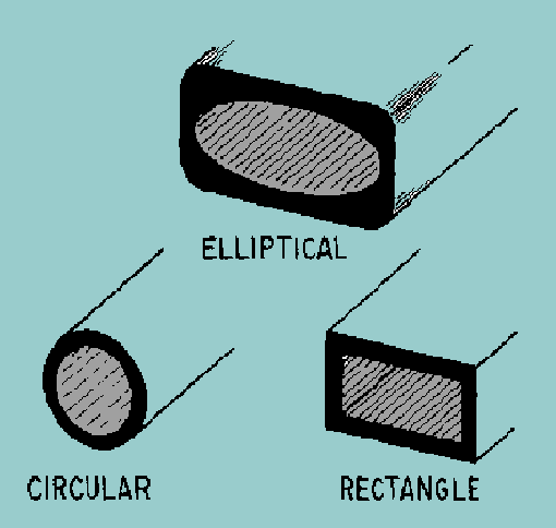
Limited Flexibility
Waveguides are notoriously rigid, making them a poor fit for dynamic or compact systems. A standard WR-90 waveguide (for X-band frequencies) has a bending radius of at least 30 cm, meaning it cannot be twisted or folded like coaxial cables. Trying to force a tighter bend beyond 15° per meter risks permanent deformation, increasing signal loss by 0.5-2 dB per bend. In comparison, a flexible coaxial cable (e.g., LMR-400) can bend down to 5 cm radius with negligible performance impact.
The stiff structure also complicates routing. In aircraft or satellite systems, where space is tight (often < 10 cm clearance), waveguides require custom elbow joints (45° or 90°), each adding $50-200 and 0.2-0.5 dB of insertion loss. If a waveguide must snake around obstacles, engineers often need multiple sections joined with flanges, which increase weight (by 10-20% per joint) and raise failure risks from vibration or thermal cycling.
Thermal expansion worsens the problem. Aluminum waveguides grow by 0.12 mm per meter for every 10°C temperature rise. In outdoor installations (e.g., radar towers), where temperatures swing 40-60°C annually, a 10-meter waveguide can expand or contract 5-7 mm, stressing mounts and flanges. Without sliding joints ($150-300 each), this leads to misalignment (+0.3-1 dB loss) or even mechanical failure.
| Flexibility Limitation | Impact | Workaround Cost |
|---|---|---|
| Minimum bend radius (30 cm) | +0.5-2 dB loss if violated | $50-200 per elbow joint |
| Thermal expansion (0.12 mm/m/°C) | Misalignment, mechanical stress | $150-300 per sliding joint |
| Weight (5-15 kg/m) | Requires heavy-duty supports | $20-100 per additional bracket |
| Multi-joint routing | +0.1-0.3 dB loss per flange | $200-500 for precision alignment |
Weight is another constraint. A 3-meter copper waveguide can weigh 15-45 kg, forcing reinforced mounting structures that add $50-200 per support. In mobile systems (e.g., military vehicles), this cuts into payload capacity—every 10 kg of waveguide reduces available equipment space by 2-5%.
Flexible waveguides exist, but they trade performance for bendability. A corrugated copper waveguide can bend to 10 cm radius, but its loss jumps to 1-3 dB/m (vs. 0.1-0.5 dB/m for rigid types). For high-power applications (> 500 W), flexible designs also overheat faster, limiting duty cycles to 70-80% of rigid waveguides.
Signal Loss Issues
A standard copper WR-90 waveguide at 10 GHz typically has a theoretical loss of 0.08 dB/m, but in practice, this climbs to 0.12-0.25 dB/m due to surface roughness, oxidation, and flange misalignments. Over a 50-meter run, that adds up to 6-12.5 dB of loss—enough to halve signal power multiple times.
The primary culprits behind excess loss include:
- Surface roughness (Ra > 0.8 µm) – Increases loss by 0.02-0.05 dB/m due to scattering.
- Moisture/dust ingress – Raises attenuation by 0.1-0.3 dB/m in humid environments.
- Poor flange alignment (> 0.5 mm offset) – Adds 0.3-1 dB per connection.
- Bends & deformations – Tight bends beyond 15° per meter introduce 0.5-2 dB loss per turn.
Copper waveguides degrade over time. Without proper plating, copper oxidizes at ~0.1 µm/year in humid air, increasing loss by 3-8% annually. Silver-plated waveguides resist corrosion better (< 0.01 µm/year oxidation), but the plating adds 20-30% to the cost and wears off at friction points (flanges, joints) after 5-7 years of use. In high-power systems (> 1 kW), surface pitting from arcing can double the loss in just 2-3 years.
Frequency plays a huge role. At 24 GHz (5G mmWave), loss jumps to 0.3-0.6 dB/m due to higher skin effect resistance. For 60 GHz applications, it worsens to 1-1.5 dB/m, forcing shorter runs (< 10 m) or expensive low-loss alternatives like air-dielectric waveguides (0.05-0.1 dB/m, but $1,000+/m).
Mitigation isn’t cheap. Polishing internal surfaces to Ra < 0.4 µm cuts loss by 15-20%, but adds 50-150 per joint) prevent moisture ingress but require annual maintenance. For critical systems, active cooling (20-30 W per meter) keeps temperatures stable, reducing thermal expansion-induced misalignment—but at a $300-600/m energy and hardware cost.
Alternatives like RF-over-fiber offer lower loss (< 0.05 dB/m) but max out at 50 W power, making them useless for radar or industrial heating. Until waveguide materials improve, engineers must live with these losses—or pay a premium to minimize them.
Heavy and Bulky
Waveguides are not lightweight components—their rigid metal construction makes them significantly heavier and bulkier than coaxial cables or fiber optics. A standard 1-meter copper WR-90 waveguide weighs 3-5 kg, while an equivalent LMR-400 coaxial cable is just 0.3 kg per meter. In large installations, like satellite ground stations, a 50-meter waveguide run can add 150-250 kg of weight, requiring reinforced mounting structures that increase installation costs by 20-40%.
The sheer size of waveguides also creates problems. A WR-284 waveguide (for S-band frequencies) has internal dimensions of 72 x 34 mm, making it too wide for tight spaces like server racks or drone avionics. In comparison, a semi-rigid coaxial cable with similar performance might be just 10 mm in diameter. This bulk forces engineers to redesign equipment layouts or sacrifice space for other components.
Key weight and size challenges include:
- Transportation difficulties – Shipping 10-meter waveguide sections requires custom crates (+$200-500 per shipment) due to their length and fragility.
- Structural reinforcement – Mounting 50+ kg waveguide arrays on towers or aircraft demands steel supports (+$50-150 per bracket) to prevent sagging.
- Space constraints – In 5G mmWave base stations, waveguide routing consumes 30-50% more space than RF-over-fiber alternatives.
- Labor intensity – Installing heavy waveguide sections (10-15 kg each) often requires two technicians, doubling labor costs.
Material choices don’t help much. Aluminum waveguides are 30-40% lighter (2-3 kg/m) than copper, but they’re weaker and more prone to denting—a 1-2 mm dent can increase loss by 0.5-1 dB. Some aerospace applications use thin-wall titanium waveguides (1.5-2 kg/m), but these cost $800-1,200 per meter, making them prohibitively expensive for most projects.
Weight directly impacts performance in mobile systems. On a military drone, every extra kilogram of waveguide reduces flight time by 2-3 minutes. In automotive radar (77 GHz), bulky waveguides force compromises in sensor placement, limiting field of view by 5-10°. Even in data centers, where space is critical, waveguide routing blocks airflow, increasing cooling costs by 8-12%.
Alternatives like dielectric waveguides are lighter (0.5-1 kg/m) and thinner (10-20 mm diameter), but they struggle with high power (> 100 W) and have higher loss (0.5-1 dB/m). Until compact, low-weight designs improve, engineers must work around the bulk—or accept the trade-offs.
Complex Repairs
Waveguides are notoriously difficult to fix when damaged, often requiring specialized tools, trained technicians, and lengthy downtime. A single dent or misaligned flange that would take 5 minutes to fix on a coaxial cable can demand 2-4 hours of work on a waveguide, costing 300−800 in labor and parts. In critical systems like airborne radars or satellite communications, waveguide failures can halt operations for 24−48 hours, leading to 10,000+ per day in lost revenue.
The main repair challenges stem from waveguides’ precision construction. A 0.5 mm deformation in a WR-90 copper waveguide can increase signal loss by 0.3-1 dB, while corrosion or oxidation at flange joints degrades VSWR by 10-20%. Unlike flexible cables that can be spliced or patched, damaged waveguide sections usually need complete replacement, which means:
- Custom fabrication delays – Lead times for non-standard waveguide lengths range from 2-6 weeks.
- Precision realignment – Flanges must be resurfaced (flatness < 0.02 mm) to prevent leaks, adding $150-300 per joint.
- System recalibration – After repairs, full RF testing is needed, consuming 1-3 hours of $100-200/hour technician time.
| Repair Scenario | Typical Time Required | Cost Range | Performance Impact |
|---|---|---|---|
| Flange resealing | 1-2 hours | $200-500 | VSWR improves by 5-15% |
| Section replacement (1 m) | 3-5 hours | $600-1,200 | Loss reduced by 0.5-2 dB |
| Dent removal & polishing | 2-4 hours | $400-900 | Attenuation drops 0.3-0.8 dB |
| Full system recalibration | 4-8 hours | $800-1,500 | Restores original specs ±0.2 dB |
Moisture damage is especially costly. If water infiltrates a waveguide (common in marine or humid environments), the internal silver plating corrodes at 0.1-0.3 µm/month, increasing loss by 0.2-0.5 dB per year. Full dehumidification and replating costs $1,000-2,500 per meter and requires system shutdown for 3-5 days.
Field repairs are nearly impossible for rigid waveguide systems. Technicians often must disassemble entire arrays to access a single damaged section. In 5G mmWave base stations, replacing a 10 cm waveguide segment can take 6-8 hours due to tight integration with antenna panels.
Narrow Frequency Range
Waveguides are not broadband devices—each type is designed to work only within a strict frequency window, typically ±15-20% of its center frequency. A WR-90 waveguide (for X-band) operates efficiently from 8.2-12.4 GHz, but outside this range, performance deteriorates rapidly. At 7 GHz, its attenuation spikes to 3-5 dB/m (vs. 0.1 dB/m at 10 GHz), while at 13 GHz, unwanted higher-order modes create standing waves that distort signals by 15-25%. This forces engineers to use multiple waveguide types in systems requiring wide bandwidth, increasing costs by 30-50% and complicating RF path design.
Example: A dual-band radar system operating at 5 GHz (C-band) and 15 GHz (Ku-band) needs two separate waveguide runs (WR-187 and WR-62), doubling the weight (from 10 kg to 20 kg for 5 meters) and installation complexity.
The narrowband nature stems from waveguide physics. Below the cutoff frequency (determined by the width-to-height ratio), signals cannot propagate—a WR-112 waveguide (for Ku-band) simply won’t transmit anything below 14 GHz. Above the upper frequency limit, multiple modes compete, causing phase errors up to 10-30° per meter. For wideband signals like 5G NR (100-400 MHz bandwidth), this creates group delay variations of 1-5 ns/m, enough to degrade modulation accuracy by 3-8 dB EVM.
Material choices don’t solve the problem. While dielectric-loaded waveguides can extend bandwidth by 5-10%, they increase loss by 0.2-0.5 dB/m. Elliptical waveguides (rare and expensive at 200-400 per connection. Even then, their peak performance is 10-15% worse than standard rectangular waveguides.
Real-world impacts are severe. In satellite ground stations, where 4-18 GHz coverage is common, operators must install 3-4 parallel waveguide systems, consuming 60-80% more space than a comparable coaxial cable setup. For software-defined radios that dynamically switch between 2-6 GHz, waveguides are practically unusable—their effective bandwidth is less than 500 MHz per type, forcing electromechanical switches that wear out after 50,000 cycles (2-3 years of heavy use).
Alternatives like TEM-mode coaxial lines handle DC to 18 GHz in a single cable, but max out at 100 W power. Substrate-integrated waveguides on PCBs offer 5-8 GHz bandwidth but suffer 1.5-3 dB/m loss. Until breakthroughs in metamaterial waveguides mature, engineers must live with these frequency constraints—or pay dearly to work around them.


