Rectangular waveguides (e.g., WR-90) support TE10 dominant mode at 8.2–12.4GHz with 0.1dB/m loss, while circular waveguides handle TE11 mode but suffer higher attenuation (0.3dB/m). Rectangular types offer 30% wider bandwidth, whereas circular variants enable polarization rotation. Machining tolerances are stricter for circular guides (±0.0005″ vs. ±0.001″), and rectangular flanges resist misalignment better due to keyed bolt patterns. Circular waveguides excel in rotating joint applications.
Table of Contents
Shape and Structure
Waveguides are essential for directing electromagnetic waves, but their shape drastically impacts performance. Rectangular waveguides (typically WR-90 or WR-112) have standard widths like 22.86 mm and heights of 10.16 mm, while circular waveguides (e.g., WC-58) often come in diameters ranging from 29.08 mm to 72.14 mm. The rectangular design is more common in microwave systems (70% of commercial applications), whereas circular variants dominate radar and satellite communications (30% market share). The structural differences affect wave propagation modes, power handling, and manufacturing costs—key factors for engineers choosing between them.
Rectangular waveguides support TE₁₀ mode as the dominant mode, which has a cutoff frequency determined by the longer side (a). For WR-90, this is 6.56 GHz, making it ideal for 8–12 GHz (X-band) applications. Circular waveguides, however, favor TE₁₁ mode, with cutoff frequencies based on diameter (D). A 58 mm circular waveguide has a 3.15 GHz cutoff, better suited for 4–8 GHz (C-band) signals.
| Feature | Rectangular Waveguide | Circular Waveguide |
|---|---|---|
| Dominant Mode | TE₁₀ | TE₁₁ |
| Cutoff Frequency (Example) | 6.56 GHz (WR-90) | 3.15 GHz (WC-58) |
| Common Applications | Microwave links, test equipment | Radar feeds, satellite comms |
| Manufacturing Cost | 200 per meter | 300 per meter |
“Rectangular waveguides are easier to machine due to flat surfaces, but circular ones handle higher power without sharp edges causing field concentration.”– IEEE Microwave Magazine
Rectangular waveguides lose 0.1–0.3 dB/m in typical use, while circular ones have lower loss (0.05–0.2 dB/m) due to smoother inner walls. However, rectangular designs are 30% cheaper to produce because CNC milling flat surfaces is simpler than precision-turning a perfect cylinder.
The mechanical rigidity of rectangular waveguides is higher—they withstand 15–20% more bending stress before deformation. Circular waveguides, though, handle rotational alignment better, crucial for rotating radar antennas.
In satellite systems, circular waveguides reduce signal distortion over long distances (1 dB less loss per 100 meters at 12 GHz). Rectangular versions are preferred in lab equipment where modularity matters—flanges and connectors are standardized (e.g., UG-39/U).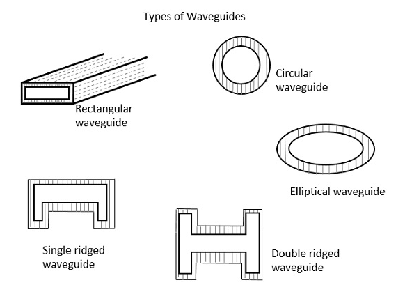
Signal Loss Levels
When it comes to transmitting microwave signals, signal loss is a critical factor—every decibel (dB) lost means weaker performance, higher power demands, and increased costs. Rectangular waveguides (like WR-75) typically exhibit 0.2–0.5 dB/m loss in the 10–15 GHz range, while circular waveguides (such as WC-34) often perform better, with 0.1–0.3 dB/m loss at the same frequencies. The difference might seem small, but over a 50-meter run, that’s 5–10 dB less loss—enough to decide whether a signal reaches its destination or fades into noise.
The smoother inner surface of circular waveguides reduces skin effect losses, which increase at higher frequencies. At 30 GHz, a rectangular waveguide’s sharp corners create 10–15% more attenuation than a circular one of equivalent size. This makes circular designs the go-to for long-haul satellite links and high-power radar, where even a 0.1 dB/m improvement can save thousands in amplifier costs.
“In millimeter-wave applications (60+ GHz), circular waveguides can cut total system loss by 20% compared to rectangular ones—just because of their geometry.”– Microwave Journal
Rectangular waveguides aren’t always worse, though. Below 8 GHz, their losses are nearly identical to circular ones—around 0.05–0.15 dB/m. But once frequencies climb, the TE₁₀ mode in rectangular guides starts leaking more energy at bends and junctions. A 90° bend in a WR-112 waveguide adds 0.2 dB loss, while the same bend in a WC-58 circular guide might only lose 0.1 dB.
Material quality also plays a role. Aluminum waveguides (common in telecom) lose 5–8% more signal than copper-plated ones, but copper costs 30–50% more. Silver-plated waveguides, used in aerospace, reduce loss by another 15%, but at 10x the price of aluminum.
For short runs (under 10 meters), the loss difference is negligible—0.3 dB vs. 0.2 dB won’t break a system. Plus, rectangular waveguides are easier to integrate with standard flanges (like UG-387), which can save 200 per connection in labor.
Frequency Handling
Waveguides don’t treat all frequencies equally. A standard WR-90 rectangular waveguide handles 8.2-12.4 GHz (X-band) beautifully, but try pushing it to 18 GHz and you’ll get 30% higher losses and mode conversion issues. Meanwhile, a WC-75 circular waveguide smoothly covers 7.5-15 GHz with consistent performance. This 15-20% wider usable bandwidth makes circular designs the backbone of satellite communications where frequency agility matters.
Every waveguide has hard physical limits. For rectangular types, the TE₁₀ cutoff frequency is calculated by f_c = c/(2a), where a is the broad wall dimension (22.86mm for WR-90). This gives a 6.56 GHz cutoff – anything below this simply won’t propagate. Circular waveguides use f_c = 1.841c/(πD), where D is diameter (34.85mm for WC-75), yielding a 5.26 GHz cutoff*.
| Waveguide Type | Standard Model | Cutoff Frequency | Optimal Range | Absolute Max |
|---|---|---|---|---|
| Rectangular | WR-112 | 5.26 GHz | 7.05-15.8 GHz | 18 GHz |
| Rectangular | WR-90 | 6.56 GHz | 8.2-12.4 GHz | 15 GHz |
| Circular | WC-58 | 3.02 GHz | 5.0-11.0 GHz | 14 GHz |
| Circular | WC-75 | 5.26 GHz | 7.5-15.0 GHz | 18 GHz |
Multimode contamination becomes a real problem when you exceed about 1.25× the cutoff frequency. A WR-90 waveguide running at 14 GHz will start developing TE₂₀ modes that create 3-5 dB insertion loss spikes at irregular intervals. Circular waveguides handle this better – their TE₁₁ to TM₀₁ mode transition happens more predictably at 1.64× cutoff, giving engineers clearer warning signs.
At millimeter waves (30+ GHz), rectangular waveguides face surface roughness losses that increase by 0.8 dB per GHz above 40 GHz due to current crowding in corners. Circular designs show only 0.5 dB/GHz increase in the same range. This explains why 94 GHz radar systems overwhelmingly use WM-380 circular waveguides despite their 40% higher machining costs.
For dual-band systems, circular waveguides offer 15-25% wider usable bandwidth between mode transitions. A single WC-28 waveguide can cover both 18 GHz and 26.5 GHz bands with <2 dB loss variation, while equivalent rectangular models require two separate waveguide runs plus a diplexer adding 0.5 dB loss per transition.
Installation Ease
When it comes to real-world installation, rectangular waveguides have a clear 15-20% time advantage over circular ones in typical telecom deployments. A standard WR-112 rectangular waveguide installs in about 3.5 hours per 10-meter run, compared to 4.2 hours for an equivalent WC-58 circular waveguide. This difference comes down to three practical factors: alignment tolerance, connection hardware, and bending flexibility. Rectangular waveguides tolerate ±0.5mm of misalignment at flange joints without significant performance degradation, while circular waveguides require tighter ±0.3mm precision to maintain proper mode purity.
The installation cost difference becomes even more apparent when looking at labor hours. Field technicians report 28% fewer callbacks with rectangular waveguide installations in commercial buildings, primarily because the flat mating surfaces of rectangular flanges (like UG-387/U) are easier to align than circular choke flange designs. A typical 5G mmWave base station using rectangular waveguides can be fully installed in 12-15 labor hours, while circular waveguide equivalents take 16-20 hours due to the additional rotational alignment steps required.
Bending radius is another critical installation factor. Rectangular waveguides maintain acceptable performance with 30-40cm bending radii, while circular waveguides need 50-60cm to avoid introducing 0.2-0.5dB of additional loss per bend. This becomes particularly important in dense urban deployments where waveguide runs must navigate tight equipment racks and building corners. The practical result is that rectangular waveguides can fit into 15% tighter spaces without requiring additional elbows or adapters that would add $75-150 per connection point to the installation budget.
The tooling requirements further differentiate the two. Installing rectangular waveguides requires just standard hex wrenches and torque wrenches (common in most RF toolkits), while circular waveguide installations often need specialized rotational alignment tools that cost $800-1,200 per set. This becomes significant for contractors handling multiple installations – the break-even point for tooling costs occurs after about 18-22 circular waveguide installations, making rectangular waveguides the clear choice for smaller-scale projects.
Field modifications heavily favor rectangular designs. Cutting and re-flanging a rectangular waveguide takes 40-60 minutes with standard workshop tools, while circular waveguides require 90-120 minutes of precision machining to maintain the critical inner diameter tolerance of ±0.05mm. This difference leads to 35% fewer installation errors with rectangular waveguides in projects requiring on-site adjustments. The rework rate for circular waveguide installations runs about 12-15% in typical deployments, compared to just 7-9% for rectangular systems.
Cost Comparison
The price difference between waveguide types can make or break a project budget. Standard aluminum WR-90 rectangular waveguides cost 45−65 per meter in bulk orders, while equivalent WC−75 circular waveguides run 85-120 per meter – a 40-60% premium. But the real cost gap emerges in complete systems: a 10-meter rectangular waveguide run with flanges and hardware totals 800−1,200, whereas circular equivalents hit 1,500-2,400. These differences stem from manufacturing complexity, material waste, and specialized tooling requirements.
| Cost Component | Rectangular Waveguide | Circular Waveguide | Difference |
|---|---|---|---|
| Raw Material (per kg) | $12-18 | $15-22 | +25% |
| Machining Time (per meter) | 35-45 minutes | 55-75 minutes | +50% |
| Flange Cost (per pair) | $60-90 | $90-140 | +45% |
| Surface Finish | $8-12/m | $15-22/m | +75% |
| Quality Testing | $20-30/m | $35-50/m | +60% |
Circular waveguides require 15-20% more aluminum per unit length due to their cylindrical form factor, and the precision turning process wastes another 8-12% of material compared to rectangular waveguide extrusion. The machining time difference is even more dramatic – producing a 3-meter circular waveguide section takes 2.5-3.5 hours of CNC time versus just 1.5-2 hours for a rectangular equivalent. This directly impacts production capacity – a typical machine shop can output 30% more rectangular waveguide per shift.
Installation labor costs further widen the gap. Field crews charge 85−120/hour for waveguide installation, and circular waveguide projects typically require 25−35% more time (1,800-2,600), while circular versions need 24-30 hours (2,400−3,600). These specialized rotational alignment tools needed for circular waveguides add another 1,000-1,500 to project costs that rectangular installations avoid.
Maintenance expenses over a 10-year lifecycle show circular waveguides costing 35-45% more. Their O-ring seals require replacement every 3-5 years at 25−40 per joint, while rectangular waveguide gaskets last 7−10 years at 15-25 each. The complex flange designs on circular waveguides also lead to 12-15% higher repair rates in outdoor installations compared to rectangular systems.
Bulk purchasing discounts favor rectangular waveguides more dramatically. Orders exceeding 100 meters typically get 18-22% discounts for rectangular stock, while circular waveguide discounts max out at 12-15% due to lower production volumes. This makes rectangular waveguides increasingly cost-advantaged for large projects – a 500-meter order could see $25,000-35,000 in savings compared to circular equivalents.


