Table of Contents
Wave Propagation in Waveguides
Wave propagation in waveguides is a fundamental aspect of modern telecommunication and microwave engineering domains. The ability to guide electromagnetic waves along the specified path allows for convenient signal transmission and reception without losses during the entire medium. The nature of waveguides as such is obviously logical, with the guiding structure confining the waves within the boundaries formed by conductive metals or other dieletric materials. The type of waves and their characteristics are defined by the nature of the waveguide, with different shapes and sizes supporting various regimes. Depending on the structure and material, rectangular waveguides typically guide TE and TM waves, while the circular shape allows for TE, TM, and TEM modes . For instance, a TE10 wave can be guided within a 2.286 x 1.016 mm (x-y) rectangular waveguide at around 10 GHz . By increasing or decreasing the geometry of the waveguide, the operating frequencies can be effectively increased or decreased.
In terms of influence, there are also several critical parameters defining wave propagation, with phase velocity and group velocity being the two important ones . The former refers to the speed of the wave’s phase as it travels along the waveguide, and for some modes, it can be greater than the speed of light in space. The latter is actual speed, with the group traveling well below the speed of sound in space. In other words, the group velocity according to its name refers to the speed at which energy travels along the medium. Material and shape are another major factor affecting the wave propagation, with the loss element being a critical aspect of any new guide property. Silver is the most suitable material to use due to its minimum resistance losses, while aluminum or copper is used frequently due to the reduced cost to build waveguides. Overall, it can be said that waveguides are used in a variety of technologies and applications, with properly designed and optimized waveguides not losing more than 0.2 db per kilometer of the fiber. Trace signal propagation may be hampered by a variety of issues. One such case is the presence of radiation, which may lead to phase losses as the waves disperse throughout space or interfere with the medium’s internal properties, leading to damping. Finally, the dispersion effect can broaden the duration of the signal, reduce the data transmission rate, and impact the signal integrity. To prevent such effects when necessary, silicone and fiber-based materials are used to guide the waves within the optimal limits, reducing the latency and attenuation rate.
Maxwell’s Equations in Waveguides
Maxwell’s equations define the bedrock of electromagnetic theory and provide valuable insight into the behavior of electromagnetic fields in waveguides. Being confined within the space of a waveguide, Maxwell’s equations define not only the conditions of existence but also the conditions that the fields must satisfy to exist under given materials that make up the boundary conditions of the waveguide . There are four equations that generalize and describe the behavior of electric and magnetic fields about the distribution of electric charges and currents. When applied to the physics of a waveguide, this means that it is possible to determine various aspects of the wave propagation, such as cross-sectional modes, phase velocities, and the existence of standing waves. The most important parameter predicted by the Maxwell equations is that to have wave propagation in a waveguide, the electromagnetic fields must satisfy the boundary conditions at the surface of the waveguide.
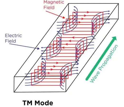
Maxwell’s equations are able to predict the existence of two major modes in a waveguide. These modes are the TE and TM modes, which provide information about the orientation of the electric and magnetic field , such as it being perpendicular to the direction of wave propagation or lateral, respectively. For example, rectangular waveguides possess the two modes where the TE and TM modes are valid at any frequency. However, the two modes may not exist above a particular frequency determining the cutoff frequency. For TE10 mode in a standard rectangular waveguide with the width b = 2.286 cm, for the TE10 mode, the cutoff frequency is given as 6.56 GHz . Thus, the above parameter is vital as it determines the frequency at which a particular mode may exist in a waveguide. The operation of waveguides is largely determined by their geometry and size. The energy and signal transmission efficiency are also influenced because some modes may require larger cross-sections to propagate over a certain frequency. There are also limitations with material properties at low or high frequencies. The waveguides may also suffer in performance when exposed to harsh environments, and such effects must be determined during testing and implementation. Some of the technologies employed include the use of metamaterials to manufacture materials that have not been available previously. In telecommunications, components have been miniaturized through the application of mode couplers to control material waveguides. The manufacture of laser frequencies also requires the use of appropriate waveguides containing a combination of materials. Additionally, metamaterials can be used in medical imaging to determine bones by controlling the frequency and power modes at which the waves interact with the bone. Similarly, controlling them increases the flexibility of the design process. Mysteriously, lenses for sensors could be manufactured with metamaterials, an application that has not been possible with natural materials.
Boundary Conditions
The study of electromagnetic waves in waveguides cannot exist without a comprehensive understanding of what phenomenon occurs at their boundaries. That is to say, how electromagnetic fields behave at the interfaces between adjacent materials, which are the waveguide’s walls. Thus, boundary conditions are enforceable in studying waveguides in terms of figuring out what modes of propagation may be and how to calculate their respective fields within the guide.
Role of Boundary Conditions in Wave Propagation
Boundary conditions are derived from Maxwell’s equations by assuming the geometry of the waveguide. They state that the tangential part of the electric fields must remain continuous across boundaries, while the normal part of displacement fields D and tangential to the boundary magnetic fields H must adjust to the surface charge and free current along the surface of the waveguide. For instance, for proper metallic waveguides, the tangential electric fields will be zero at conducting surfaces to make the normal components of D zero too. The lack of tangential electric fields poses a condition for wave propagation in discrete modes, emphasizing the difference between TE or Transverse magnetic modes and the others.
Waveguide Design
In practice, boundary conditions affect waveguide design in two essentially important ways. Firstly, they are responsible for the cutoff frequency of each mode, with the degree of their influence increasing as the number of modes considered increases. The cutoff frequency determines what mode can be supported in a rectangular waveguide. The TE10 mode that occupies the waveguide space for the longest period of time has a cutoff frequency that is the least of all available modes. Thus, to support a higher number of modes, one creates a waveguide of smaller devices, as modes of propagation for higher frequencies exist. However, these guides are harder to design and manufacture. Secondly, boundary conditions dictate the cutoff diameter of a waveguide, which is related to the cutoff frequency. In this case, lower cutoff frequencies are more likely to be accompanied by a higher cutoff diameter.
The main challenge of these conditions is to derive particular shapes of conducting materials such that power loss in waves is commanded and, therefore, the propagation of unintended modes through waveguides at unwanted port frequency would be limited. One has to use materials with a smaller loss tangent in a waveguide. Based on this, dielectric waveguides for use in optical frequencies are used, which allow a tighter estimation of the electromagnetic waves. This, in turn, makes them less diffuse and less attenuation over a long distance. This property finds its application in internet connections between providers, with the simultaneous application as a simple guide for transmitting data being unnecessary in the absence of frequent use. The biggest waveguide advances to date are the nano-applied photonic crystal waveguides and plasmonic waveguides that control light in boundary conditions.
 Phase and Group Velocity
In the context of wave propagation through a medium, including a waveguide, the understanding of the phase and group velocities is of paramount significance. In particular, one must have a good grasp of these two notions to analyze how different characteristics of a wave move through space and how they should be designed in order for a particular communication system, radar, or any other piece of technology where waves are used, to operate properly.
Phase Velocity: Wavefront’s Speed
Phase velocity is the speed with which the wave’s individual constant phase wavefronts move through space. In simple terms, it is the velocity with which you would see the peak of a single-frequency wave moving. It is defined as ��=��vp=kω, where �ω is the wave’s angular frequency and �k is its wave number . For electromagnetic waves, the phase velocity through a vacuum is equal to that of light, or �c, which equals approximately 3 × 108108 m/s . In a waveguide, however, the phase velocity can exceed the speed of light, although it does not have real implications. This phenomenon is called superluminal speed, yet it does not actually represent the speed with which information or data can be transmitted.
Group Velocity: Pulse Propagation Speed
In its turn, the group velocity is defined as the speed at which the signal’s amplitude propagates through space. It is the speed with which a packet of waves, or the pulse, moves. It is defined as ��=����vg=dkdω. As opposed to phase velocity, group velocity through a waveguide tends to be less than the speed of light. In this case, the strictures determined by the theory of relativity are adhered to. This type of velocity is particularly relevant for communication systems as it determines the speed with which information is transmitted.
How They Work in Waveguides and Optical Fibers
The interaction between these two characteristics in a wave guide—especially in cases of high-frequency applications, such as optical fibers and microwave lines, which are widely used in communication systems—is important because in a perfectly dispersive medium, or one where phase and group velocities are equal, waves do not spread substantially during transmission. Hence, the less difference, the less dispersion, which leads to a higher number of bits transmitted per unit of time and, therefore, increased efficiency.
For example, in optical fibers, which represent a hollow tube of tens of micrometers in diameter capable of transmitting light through subsequent reflections, what is known as dispersion, or the difference between the group and phase velocities, would occasionally cause a video download to take longer than it should. This problem may be partially resolved by dispersion compensation but will always have an upper limit, which may present a major efficiency issue. The recent advancements in waveguide technology, such as photonic crystal technologies, have been focused on reducing dispersion as much as possible and finding new ways to control waveguides’ materials and shapes.