+86 29 8881 0979

April 16, 2025

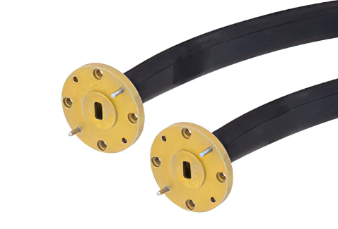
What Is a Waveguide Choke Flange Design

A choke flange suppresses RF leakage via a ​​λ/4-deep groove​​ (e.g., ​​7.5 mm for 10 GHz​​) around the mating surface. It uses ​​annular slots​​ to reflect waves, achieving ​​>30 dB return loss​​. Must maintain ​​0.05 mm flatness tolerance​​ (per ​​MIL-F-3922​​) and ​​gold-plated contacts​​ for low resistance (<0.1Ω). Common in ​​radar/WiGig systems​​. Flange Structure At 3 […]

What Is a Waveguide Choke Flange Design Read More »

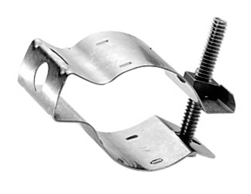
What Are Waveguide Clamp Installation Standards

Waveguide clamps must be spaced ​​≤1.5x waveguide width​​ (e.g., 30 cm for 20 cm-wide guides) per ​​MIL-STD-1678​​. Torque bolts to ​​5–7 Nm​​ to prevent deformation. Use ​​aluminum or brass clamps​​ to avoid galvanic corrosion. Ensure ​​0.5–1 mm gap​​ for thermal expansion. Ground every ​​3rd clamp​​ per ​​IEEE 287​​ to maintain RF shielding. Fixture Types Last

What Are Waveguide Clamp Installation Standards Read More »

Scroll to Top
Blank Form (#3)