June 2024

What is S1 and S2 in FTTH

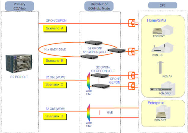
In FTTH, S1 links the central office to aggregation nodes using single-mode fiber for long distances up to 20 km. S2 connects these nodes to subscriber homes, often spanning 2-5 km. Purpose and Placement S1 and S2 are essential elements in the structure of the Fiber to the Home network, and each has a specific

What is S1 and S2 in FTTH Read More »

What is the difference between active and passive couplers

Active couplers require power to amplify signals, ideal for long distances, whereas passive couplers, power-free, split signals without amplification, suitable for short ranges. External Power Required Active couplers require an external power source to work effectively and so are quite different from their passive counterparts. This is due to the fact that, inside the box,

What is the difference between active and passive couplers Read More »

7 points to adjust the antenna for optimal reception

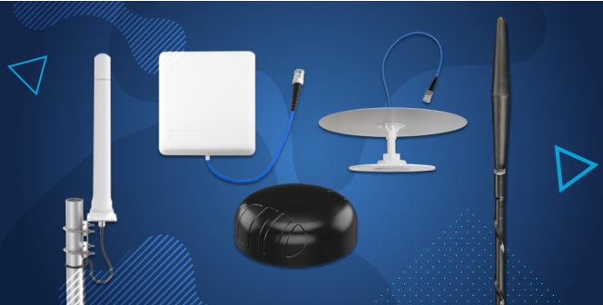
Ensure optimal antenna reception by locating broadcast towers, elevating the antenna to 30 feet, and regularly scanning for channels to capture new signals. Find Broadcast Towers For ensuring your antenna is directed in the correct orientation and position, it is critical to determine where the nearest broadcast towers are located. The websites like AntennaWeb or

7 points to adjust the antenna for optimal reception Read More »

How to integrate multiple frequency bands in antenna feed network

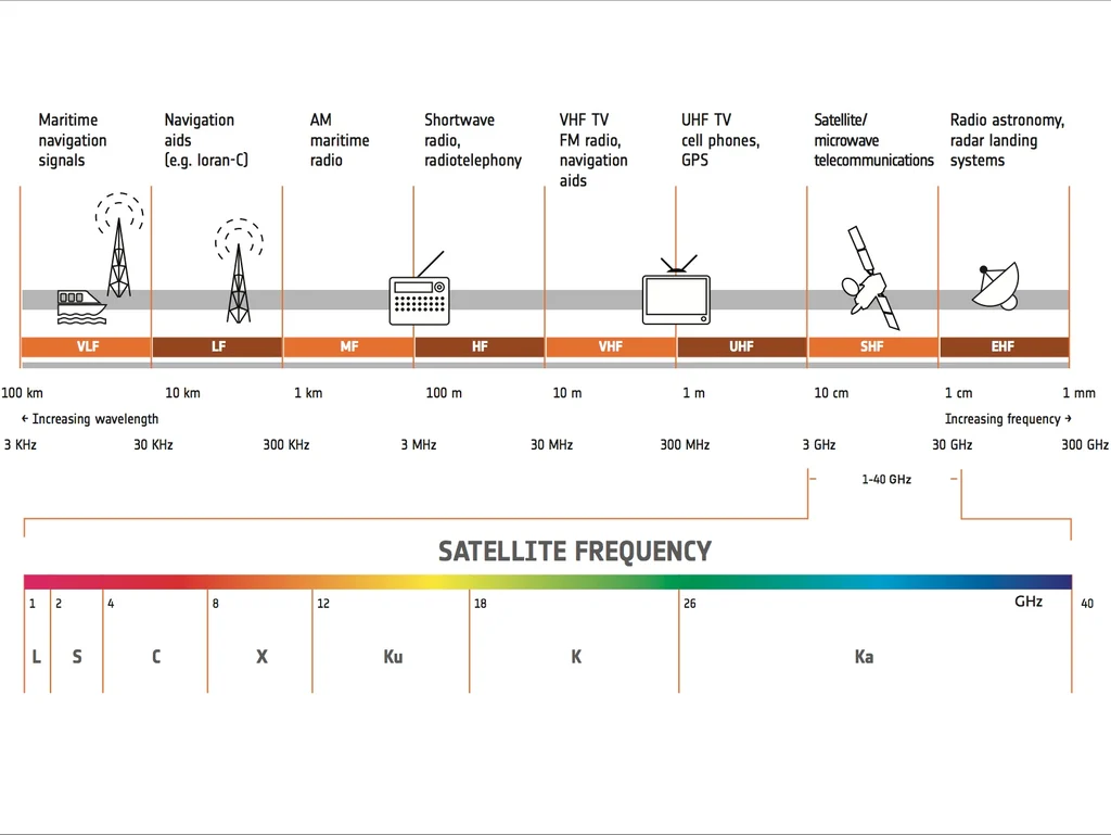
Component Selection Choosing Multi-Band Feed Systems Integrating multiple frequency bands into the antenna feed network requires the introduction of a multi-band feeding system, so the choice is to combine different frequency bands. To determine the appropriate feed system, a list of frequency bands owned by the network needs to be compiled, which can be, for

How to integrate multiple frequency bands in antenna feed network Read More »

6 Key Points on the Phase Difference in Directional Couplers

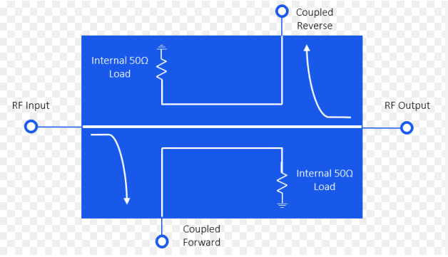
Directional couplers typically create a 90-degree phase difference between outputs, crucial for precise signal processing in applications like 5G networks operating at 28 GHz. Fundamental Design Directional couplers are critical elements in the RF and microwave engineering, which are designed to split the input signal with a defined phase difference, primarily 90 degrees. Such configuration

6 Key Points on the Phase Difference in Directional Couplers Read More »

6 key points about ideal directional coupler directivity

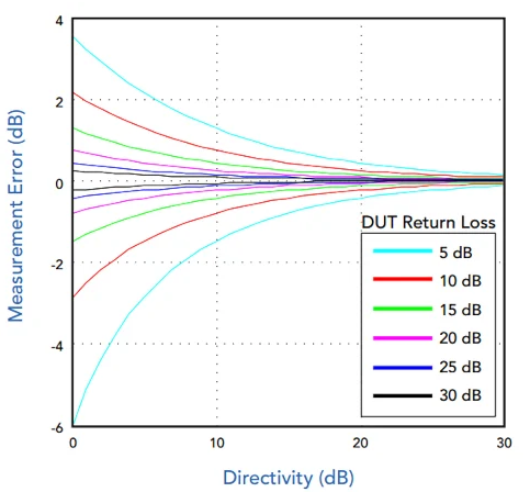
Ideal directional coupler directivity should be infinite, ensuring perfect signal isolation with high values like 30-40 dB, enhancing measurement accuracy, preserving signal integrity, enabling efficient routing, and requiring precision in design and material selection for optimal performance. Infinite Ideal The ideal directivity of a directional coupler is a theoretical concept, implying that directivity is infinite

6 key points about ideal directional coupler directivity Read More »

6 specific points to explain the coupling ratio of a directional coupler

The coupling ratio of a directional coupler, expressed in dB, measures how much input power is directed to the coupled port. For instance, -3 dB indicates that 50% of the input power is transferred, crucial for ensuring balanced signal distribution in circuit designs. Definition For such a question, it is important to note what a

6 specific points to explain the coupling ratio of a directional coupler Read More »

Scroll to Top
Blank Form (#3)