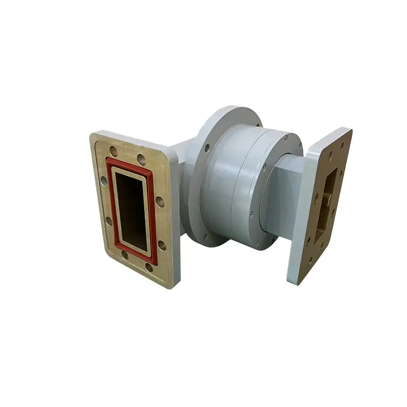
WR340 Waveguide Step Twist
Dolph Microwave waveguide twists ensure precise electrical and mechanical interfaces, particularly when mechanical packaging necessitates a change in the plane of polarization. The compact three-step twist boasts a VSWR of less than 1. 05:1 over a 10% bandwidth, while a five-step twist can achieve lower VSWR and greater bandwidth. Options for twist angles include 30, 45, and 60 degrees, with continuous twists available in smaller sizes. For commonly used materials, paint, and flange configurations, refer to the Quote Request form. Contact Mega Sales for any custom configurations needed for your high-power microwave applications.
Model DH-26WSTA500PPA
Model DH-26WSTA120PPA
WG Size WR340
Frequency Range 2450±50 MHz
VSWR 1.1:1
IL 0.1 dB
Handling Power 2 KW
Flange FDP26/FDM26 (UDR26/PDR26)
Material Al
Surface Treatment Conductive Oxidation/Silver plating
Surface Coating Anticorrosion Black CARC Painting
Twisting Type Clockwise, Step Twists
Twisting Angle 30°, 45°, 60°, 90° and other angles ( 90°as default )
Twisting Error ±0.3°
Length 120/500±0.05 mm
Waveguide twists are specialized components that manipulate the propagation of electromagnetic waves within waveguide structures by rotating their polarization. This operation primarily involves a 90-degree bend in the waveguide, which alters the phase and direction of the wavefronts as they move through it. Adjusting wave polarization is significant for various applications in telecommunications and radar systems, making waveguide twists important for effective signal transmission.
As electromagnetic waves travel within a waveguide, their behavior is influenced by the guide’s dimensions and material properties. Encountering a twist introduces a calculable phase shift, modifying the wave’s effective propagation constant, which can enhance overall transmission performance. A solid grasp of Maxwell’s equations, which describe electromagnetic theory, deepens understanding of how these twists manage wave propagation effectively.
Furthermore, waveguide twists are designed with specific materials and dimensions to minimize signal loss. Careful engineering is required to prevent unwanted reflections or scattering that could compromise signal integrity. By optimizing geometry and selecting suitable dielectric materials, waveguide twists achieve high efficiency, proving essential in advanced communication systems.
Waveguide twists are instrumental in enhancing signal integrity and polarization control across various communication systems. They ensure a consistent polarization state, significantly improving the quality and strength of signal reception, which ultimately leads to better clarity and reduced error rates, enhancing overall system performance. These twists have crucial applications in telecommunications, particularly in satellite communication systems, where signal integrity is vital. Additionally, they improve radar detection capabilities by manipulating radar wave polarization and reducing interference. In medical imaging, such as MRI, waveguide twists enhance imaging signal quality for clearer visualizations. Furthermore, they are essential in scientific research, enabling advanced experiments in quantum optics and radio astronomy through precise wave manipulation.

