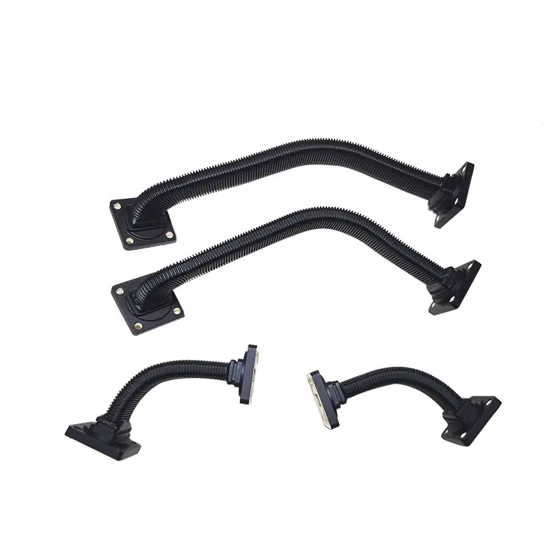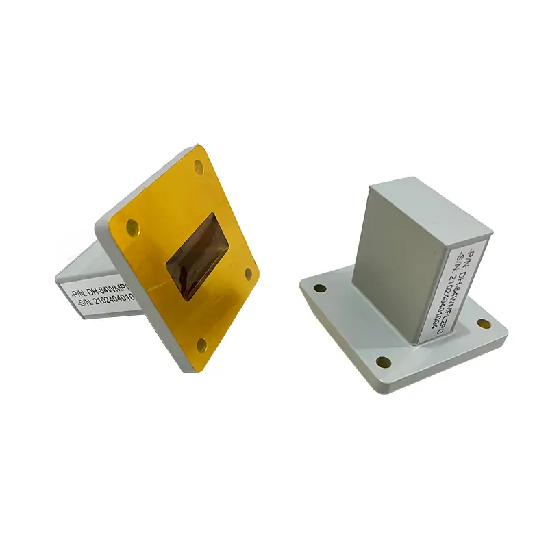
Waveguide Termination
A waveguide termination is a device used to absorb microwave energy in a waveguide system. It prevents the reflection of signals, ensuring that the waveguide operates effectively by terminating the line with its characteristic impedance. This component is crucial for maintaining signal integrity and system performance.
Dolph Microwave specializes in providing a comprehensive range of waveguide terminations, also known as dummy loads, designed to cater to a wide frequency range from 0.3 to 50 GHz. These terminations are engineered to handle low, medium, and high power inputs efficiently, making them an essential component for a variety of waveguide systems. With a focus on performance, durability, and versatility, Dolph Microwave’s terminations meet the rigorous demands of modern RF and microwave applications.
Key Features
- Broad Frequency Operation: Supports a wide range from 0.32 to 50 GHz, accommodating diverse system requirements.
- Exceptional VSWR: Offers a VSWR of less than 1.05 across the full waveguide bandwidth, ensuring minimal signal reflection.
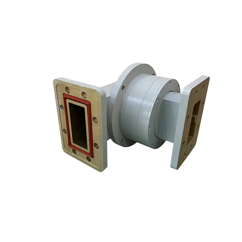
- High Power Capacity: Capable of handling up to 1,000 Watts of power input without the need for forced air cooling.
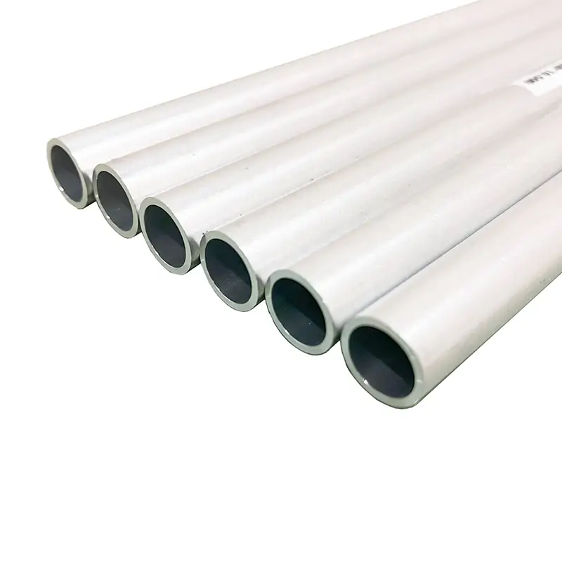
- Material Variety: Constructed from Oxygen Free Hard Copper, Copper, or Copper Alloys, providing robustness and excellent thermal performance.
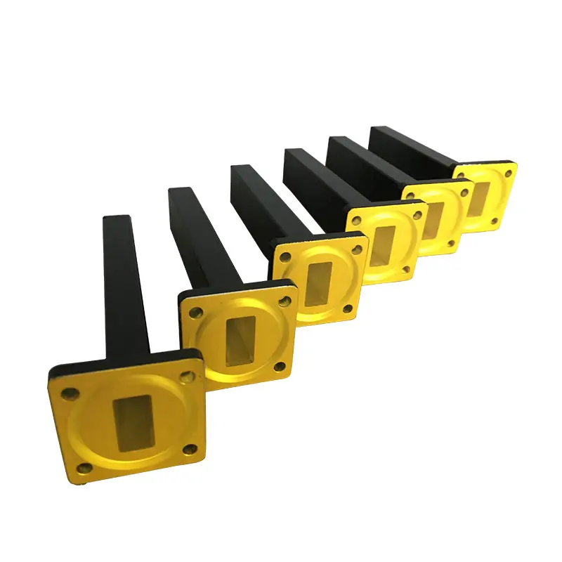
- Waveguide Size Compatibility: Available for waveguide sizes from WR-2300 to WR-22, offering flexibility for various configurations.
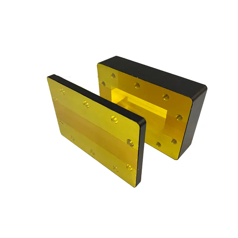
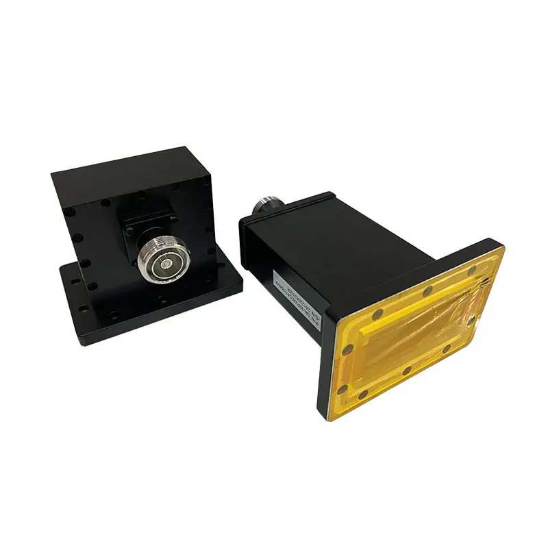
- Versatile Styles: Includes options for High Power Termination and Low Power Termination to suit specific application needs.
- Precision Engineering: Utilizes precision machining for accurate and lasting performance, guaranteeing reliability and efficiency.
- Flange Options: Features UG and CPR style flanges, enhancing connectivity and ease of installation.
Applications
Dolph Microwave’s waveguide terminations are versatile enough to be used in a wide array of applications, including:
- Telecommunications: For dissipating excess power in communication systems.
- Broadcasting: To terminate unused ports in broadcasting equipment.
- Radar Systems: Essential for absorbing reflected energy and preventing signal interference.
- Research and Development: In labs where precise measurement and testing require reliable terminations.
- Aerospace and Defense: For managing power within complex microwave systems in military and aerospace applications.
Product Specifications
Here is a concise specification table for Dolph Microwave’s waveguide terminations:
| Parameter | Specification |
|---|---|
| Frequency Range | 0.32 to 50 GHz |
| VSWR | < 1.05 |
| Average Power | 1 kW |
| Waveguide Sizes | WR-2300 to WR-22 |
| Construction | Oxygen Free Hard Copper, Copper, or Copper Alloys |
| Flange Types | UG and CPR |
Dolph Microwave’s waveguide terminations stand out for their high-quality construction, precise engineering, and ability to handle significant power levels without compromising performance. Whether for high power or low power applications, these terminations ensure reliable operation and longevity of waveguide systems.
Dolph Microwave ensures these waveguide terminations are readily available for immediate shipment, with no minimum order quantity, making it easier for projects of all sizes to access high-quality components swiftly. For customized solutions or more detailed information, Dolph’s team of sales engineers is always ready to assist, ensuring that every customer finds the perfect fit for their specific needs.
| MODEL | FREQ. RANGE (GHz) | WG SIZE | VSWR | AVG POWER CW (W) | FLANGES TYPE | LENGTH (mm) | INGRESS PROTECTION | MATERIAL | FINISH | DATASHEET | ||
| COVER | GROOVED | |||||||||||
| DH-3WL… | 0.32-0.49 | WR2300 | 1.05:1 | 5 | UDR3 | PDR3 | 2005 | IP65 | Al/Cu | Chromate/Painted | STEP | |
| DH-4WL… | 0.35-0.53 | WR2100 | 1.05:1 | 5 | UDR4 | PDR4 | 1900 | IP65 | Al/Cu | Chromate/Painted | STEP | |
| DH-5WL… | 0.41-0.62 | WR1800 | 1.05:1 | 5 | UDR5 | PDR5 | 1600 | IP65 | Al/Cu | Chromate/Painted | STEP | |
| DH-6WL… | 0.49-0.75 | WR1500 | 1.05:1 | 5 | UDR6 | PDR6 | 1300 | IP65 | Al/Cu | Chromate/Painted | STEP | |
| DH-8WL… | 0.64-0.98 | WR1150 | 1.05:1 | 5 | UDR8 | PDR8 | 1100 | IP65 | Al/Cu | Chromate/Painted | STEP | |
| DH-9WL… | 0.76-1.15 | WR975 | 1.05:1 | 5 | UDR9 | PDR9 | 660 | IP65 | Al/Cu | Chromate/Painted | STEP | |
| DH-12WL… | 0.96-1.46 | WR770 | 1.05:1 | 5 | UDR12 | PDR12 | 680 | IP65 | Al/Cu | Chromate/Painted | STEP | |
| DH-14WL… | 1.13-1.73 | WR650 | 1.03:1 | 5 | UDR14 | PDR14 | 570 | IP65 | Al/Cu | Chromate/Painted | STEP | |
| DH-18WL… | 1.45-2.2 | WR510 | 1.03:1 | 5 | UDR18 | PDR18 | 550 | IP65 | Al/Cu | Chromate/Painted | STEP | |
| DH-22WL… | 1.72-2.61 | WR430 | 1.03:1 | 5 | UDR22 | PDR22 | 470 | IP65 | Al/Cu | Chromate/Painted | STEP | |
| DH-26WL… | 2.17-3.3 | WR340 | 1.03:1 | 5 | UDR26 | PDR26 | 350 | IP65 | Al/Cu | Chromate/Painted | STEP | |
| DH-32WL… | 2.6-3.95 | WR284 | 1.03:1 | 5 | UDR32 | PDR32 | 278 | IP65 | Al/Cu | Chromate/Painted | STEP | |
| DH-40WL… | 3.22-4.9 | WR229 | 1.03:1 | 5 | UDR40 | PDR40 | 275 | IP65 | Al/Cu | Chromate/Painted | STEP | |
| DH-48WL… | 3.94-5.99 | WR187 | 1.03:1 | 5 | UDR48 | PDR348 | 170 | IP65 | Al/Cu | Chromate/Painted | STEP | |
| DH-58WL… | 4.64-7.05 | WR159 | 1.03:1 | 5 | UDR58 | PDR58 | 135 | IP65 | Al/Cu | Chromate/Painted | STEP | |
| DH-70WL… | 5.38-8.17 | WR137 | 1.03:1 | 5 | UDR70 | PDR70 | 180 | IP65 | Al/Cu | Chromate/Painted | STEP | |
| DH-84WL… | 6.57-9.99 | WR112 | 1.03:1 | 5 | UDR84/UBR84 | PDR84/PBR84 | 150 | IP65 | Al/Cu | Chromate/Painted | STEP | |
| DH-100WL… | 8.2-12.5 | WR90 | 1.03:1 | 5 | UDR100/UBR100 | PDR100/PBR100 | 130 | IP65 | Al/Cu | Chromate/Painted | STEP | |
| DH-120WL… | 9.84-15 | WR75 | 1.03:1 | 5 | UBR120 | PBR120 | 110 | IP65 | Al/Cu | Chromate/Painted | STEP | |
| DH-140WL… | 11.9-18 | WR62 | 1.03:1 | 5 | UBR140 | PBR140 | 90 | IP65 | Al/Cu | Chromate/Painted | STEP | |
| DH-180WL… | 14.5-22 | WR51 | 1.03:1 | 5 | UBR180 | PBR180 | 75 | IP65 | Al/Cu | Chromate/Painted | STEP | |
| DH-220WL… | 17.6-26.7 | WR42 | 1.03:1 | 5 | UBR220 | PBR220 | 85 | IP65 | Al/Cu | Chromate/Painted | STEP | |
| DH-260WL… | 21.7-33 | WR34 | 1.03:1 | 5 | UBR260 | PBR260 | 55 | IP65 | Al/Cu | Chromate/Painted | STEP | |
| DH-320WL… | 26.3-40 | WR28 | 1.03:1 | 5 | UBR320 | PBR320 | 40 | IP65 | Al/Cu | Chromate/Painted | STEP | |
| DH-400WL… | 32.9-50.1 | WR22 | 1.15:1 | 2 | FUGP400/UG-383U/M | 40 | IP65 | Al/Cu | Chromate/Painted | STEP | ||
| DH-500WL… | 39.2-59.6 | WR19 | 1.15:1 | 2 | FUGP500/UG-383U/M | 40 | IP65 | Al/Cu | Chromate/Painted | STEP | ||
| DH-620WL… | 49.8-75.8 | WR15 | 1.15:1 | 2 | FUGP620/UG-385U/M | 40 | IP65 | Al/Cu | Chromate/Painted | STEP | ||
| DH-740WL… | 60.5-91.9 | WR12 | 1.15:1 | 2 | FUGP740/UG-387U/M | 30 | IP65 | Al/Cu | Chromate/Painted | STEP | ||
| DH-900WL… | 73.8-112 | WR10 | 1.15:1 | 2 | FUGP900/UG-387U/M | 30 | IP65 | Al/Cu | Chromate/Painted | STEP | ||
| Part Number Guide: DH-100DRWL1.03PA5 "100"—Waveguide Size | WR90 "WL"—Waveguide Type | Precision Low Power Loads "1.03"— VSWR | 1.03:1 "P"— Flange Type | Rectangular Flat "M"— Flange Type | Rectangular Grooved "A/C"— Material | Aluminium, Cu |
||||||||||||
| Note: All Dolph-MW models include an surtec/corrosion protection treatment and are painted flat black. Flanges are unplated, polished and surtec. Other finishes and paint colors are available upon request. |
||||||||||||