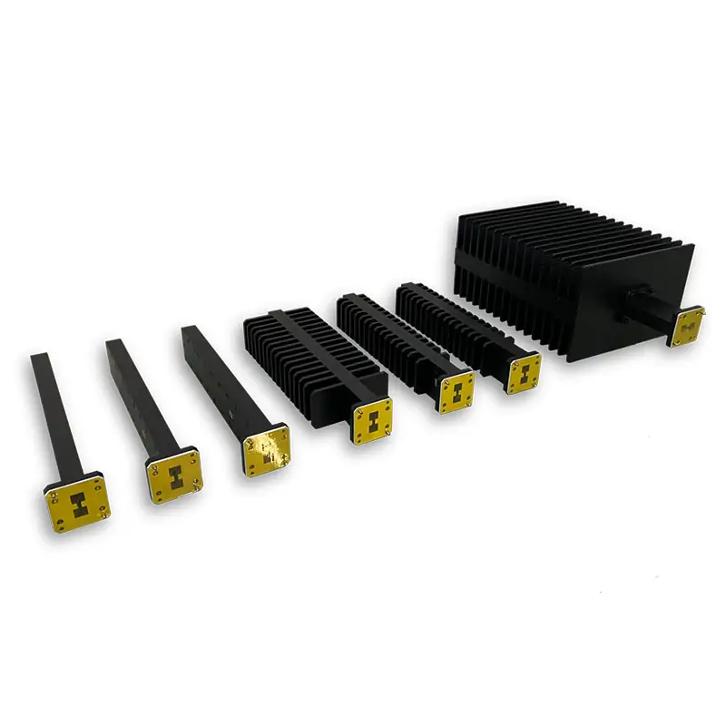
Double-Ridged Waveguide Loads & Terminations
Air- and water-cooled double-ridged waveguide loads for the listed 0.84–40.0 GHz bands, with current model-table CW ratings from 10 to 5000 W. Cover or grooved flanges, Al/Cu construction, IP65 listed models and project-specific finish options are available. Send the operating band, WRD size, CW/peak power and mating flange for model confirmation.

Match the Load to the Actual RF Conditions
The current product listing combines different WRD bands, power levels and cooling methods. Select from the model table by frequency, CW power, cooling and flange code rather than using one family value for every size.
Available Load Configurations
Use the current model matrix for high-power selection. The technical PDF also lists low-power dummy-load models for customers who need a small matched termination instead of a finned high-power load.
The downloadable load PDF lists WL1.05 dummy loads at VSWR 1.05 max. Models shown for WRD84, WRD150, WRD200 and WRD700 are rated 5 W average; WRD110 and WRD180 entries are rated 0.5 W average.
The current live table lists WHPL models from 10 W up to 5000 W CW depending on WRD size. Air or water cooling is shown on the highest-power rows.
If average and peak power are both important, use the model rating together with the actual duty cycle and cooling condition. See the waveguide power handling guide for the data to include in your RFQ.
Current Model Matrix
Model labels and specification values below are kept as published on the current product listing. Confirm the final part number, flange and power rating on the quotation or approved drawing before release.
| MODEL | FREQ. RANGE (GHz) | WG SIZE | VSWR | AVG. POWER CW (W) | COOLING METHOD | COVER FLANGE | GROOVED FLANGE | INGRESS PROTECTION | MATERIAL | FINISH | DATASHEET |
|---|---|---|---|---|---|---|---|---|---|---|---|
| DH-840DRWHPL… | 0.84-2.0 | WRD840 | 1.25:1 | 10-5000 | Air / Water Cooled | FPWRD840U24 | FMWRD840U24 | IP65 | Al/Cu | Chromate/Painted | PDF / STEP |
| DH-150DRWHPL… | 1.5-3.6 | WRD150 | 1.25:1 | 10-5000 | Air / Water Cooled | FPWRD150D24 | FMWRD150D24 | IP65 | Al/Cu | Chromate/Painted | PDF / STEP |
| DH-200DRWHPL… | 2.0-4.8 | WRD200 | 1.25:1 | 10-5000 | Air / Water Cooled | FPWRD200D24 | FMWRD200D24 | IP65 | Al/Cu | Chromate/Painted | PDF / STEP |
| DH-250DRWHPL… | 2.6-7.8 | WRD250 | 1.25:1 | 10-5000 | Air / Water Cooled | FPWRD250D30 | FMWRD250D30 | IP65 | Al/Cu | Chromate/Painted | PDF / STEP |
| DH-350DRWHPL… | 3.5-8.2 | WRD350 | 1.25:1 | 10-5000 | Air / Water Cooled | FPWRD350D24 | FMWRD350D24 | IP65 | Al/Cu | Chromate/Painted | PDF / STEP |
| DH-475DRWHPL… | 4.75-11.0 | WRD475 | 1.25:1 | 10-5000 | Air / Water Cooled | FPWRD475D24 | FMWRD475D24 | IP65 | Al/Cu | Chromate/Painted | PDF / STEP |
| DH-500DRWHPL… | 5.0-18.0 | WRD500 | 1.25:1 | 10-5000 | Air / Water Cooled | FPWRD500D36 | FMWRD500D36 | IP65 | Al/Cu | Chromate/Painted | PDF / STEP |
| DH-580DRWHPL… | 5.8-16.0 | WRD580 | 1.25:1 | 10-1000 | Air | FPWRD580D28 | FMWRD580D28 | IP65 | Al/Cu | Chromate/Painted | PDF / STEP |
| DH-650DRWHPL… | 6.5-18.0 | WRD650 | 1.25:1 | 10-1000 | Air | FPWRD650D28 | FMWRD650D28 | IP65 | Al/Cu | Chromate/Painted | PDF / STEP |
| DH-700DRWHPL… | 7.0-18.5 | WRD700 | 1.25:1 | 10-1000 | Air | FPWRD700D26 | FMWRD700D26 | IP65 | Al/Cu | Chromate/Painted | PDF / STEP |
| DH-750DRWHPL… | 7.5-18.0 | WRD750 | 1.25:1 | 10-1000 | Air | FPWRD750D24 | FMWRD750D24 | IP65 | Al/Cu | Chromate/Painted | PDF / STEP |
| DH-110DRWHPL… | 11.0-26.5 | WRD110 | 1.25:1 | 10-600 | Air | FPWRD110C24 | FMWRD110C24 | IP65 | Al/Cu | Chromate/Painted | PDF / STEP |
| DH-180DRWHPL… | 18.0-40.0 | WRD180 | 1.25:1 | 10-600 | Air | FPWRD180C24 | FMWRD180C24 | IP65 | Al/Cu | Chromate/Painted | PDF / STEP |
Part Number Guide
Example: DH-840DRWHPL100PMA
Send These Details for a Usable Quote
Built and Checked In-House
Dolph Microwave states that it has manufactured microwave components since 2001. Published factory capability includes CNC machining, turning, waveguide forming and bending, soldering and brazing, plating, anodising/passivation, abrasive machining, diamond grinding and electroforming.




Where These Loads Are Used
Engineering References & Related Components
Check CW power, peak power, duty cycle and cooling before selecting the rating. Read the power handling guide.
Use the exact flange designation and mating drawing. Review the flange size guide.
Keep flange surfaces, alignment and post-installation checks in the assembly plan. Read the installation guide.
For bends, transitions, switches, adapters and other WRD hardware, browse Double-Ridged Waveguide Components.
Send Your WRD Load Requirement
Include the frequency band, WRD size, CW/peak power, cooling, flange, material or finish, quantity and required drawings or test records.