Table of Contents
Physical Obstructions
Obstructions in the physical realm have a lot to do with radio waves, which may disrupt or weaken the signal—each depending on the type of obstacles and their density that happen to come in its path. Be it an urban, rural, or climatic changes, understanding what the various materials and settings entail provides for more effective design of solutions to be efficient in clarity and range.
The number and density of buildings, particularly high-rise concrete and steel, is one important factor in metropolitan settings. Concrete has a very high attenuation rate, weakening radio signals considerably. Assuming an average-size concrete wall, depending on its thickness, a radio wave can lose as much as 10–15 dB of signal strength per wall. For example, in a heavy urban environment with various walls in the path of both the source and receiver, there is as much as a 70% signal drop during its attempt to penetrate multiple layers of material. Added to this, of course, are metal surfaces, which are highly reflective and result in multipath interference wherein the reflected signals interfere with direct signals. In these environments, placing receivers closer to windows can minimize the damping effect of walls since glass has considerably less interfering effect on the strength of radio waves, with mere approximately 3 dB signal loss per pane.
Vegetation in natural outdoors can also interfere noticeably. Trees, especially those with high, wet foliage, tend to absorb and scatter radio waves. In fact, for the 2.4 GHz frequency band—a widely used band for wireless fidelity—a single tree may cause the loss in signal as much as around 10–15 dB; whereas in thick forest areas, a row of trees that stands together reduces the range of the signal in 2.4 GHz by almost 50% over its range in an open field. This effect is even more dramatic when it is raining or highly humid, with the added moisture acting to further enhance the absorbing abilities of the foliage. In seasonal changes such as summer, when the foliage is most dense, the degradation in signal can be up to an additional 10% to 20% compared with winter conditions, where trees have shed leaves.
Other obstacles to radio wave propagation include mountainous or hilly terrains. These are natural obstacles that radio signals find very hard to bend around, especially higher frequencies that are dependent on line-of-sight transmissions. For example, in mountainous regions, FM signals can lose about 20% to 40% if there happens to be a peak or a ridge between the transmitter and the receiver. More-sensitive UHF frequencies, such as those used in television broadcasting, fall in a range of 300 MHz–3 GHz and suffer even more, with losses potentially greater than 50% if terrain obstructs line-of-sight transmission. A broadcast tower, for example, may be located behind a hill and reach receivers on the other side by only 30% of its normal range compared to a flat area. Solutions for such areas often include positioning repeater stations on points of elevation or at intervals along valleys to maintain continuity of the signal.
Inside buildings, the structure and composition of the walls and furniture can greatly impact radio wave strength as well: partition walls provide virtually no opposition and typically generate a signal loss of only about 2 to 3 dB per wall. Conversely, metallic reinforced walls, thick concrete, or fireproofed walls can have losses as high as up to 20 dB per barrier. For example, in the typical office building, depending on the type of wall materials and exposed metal objects—perhaps a wall of filing cabinets or pipes—Wi-Fi signals operating at 5 GHz may experience drops in signal of 50% or more from the middle of the floor to corners.
Weather Conditions
These variations in radio wave propagation depend largely on the type of signal and the frequency of the transmission. Other factors that can make the clarity and range of radio signals to fluctuate are rainfall, fog, snow, and thunderstorms—all impacting radio signals, especially those of higher frequency transmissions. Such knowledge is essential in communications using radio, as weather attenuation may sometimes be heavy and it could affect the reliability of communication.
Rain is probably among the most general weather conditions that affect radio signals, and this effect increases with an increase in frequency. Above 10 GHz, rainfall attenuation becomes an issue that may affect satellite and microwave communication systems. Heavy rain of approximately 50 mm/hr intensity can depress signal strength by as much as 20 dB/km on frequencies of approximately 12 GHz. At 30 GHz, this increases to as much as 30 dB per kilometer for heavy rain. Satellite communication systems can either depend on adaptive power control to cope with this, or temporarily switch to higher transmission power during rain, which requires substantially more additional energy.
Regarding fog and humidity, these also impact high-frequency signals; however, this happens far less dramatically compared to that from rain. While the particles in fog are much finer, they could potentially cause scattering in frequencies above 20 GHz. For instance, in the case of dense fog—less than 100 meters of visibility—signals at about 30 GHz may experience attenuation levels as high as 2 to 3 dB per kilometer. In wireless communication networks utilizing this high-frequency range, such as some 5G systems, the range and reliability can be degraded by as much as 20 percent on days with fog compared to clear conditions. In addition, high humidity aggravates this effect: a 90 percent humidity can degrade the signal strength some 1 dB extra per kilometer compared with 50 percent humidity.
Snow has some variable effect on radio waves depending on the density and wetness of flakes. Dry and powdery snow generally has little if any effect on signal strength, but wet snow may cause attenuation similar to light rain. For example, for frequencies of about 15 GHz, it is possible to attenuate the signals by about 5 dB per kilometer when the moisture content in the snow mixtures is greater than about 15 %. Besides this type of signal loss, accumulating snow on antennas and transmission equipment adds reflection and refraction that serves to generally weaken the clarity of the signal. Protective housing for antennas in snowy regions reduces the effect, reducing the possibility of interference.
Thunderstorms introduce a new layer of intricacy to radio wave propagation. The most important constituent in this matter involved in thunderstorms is lightning, which produces powerful electromagnetic pulses that may interfere with radio signals on a vast frequency range. A stroke of lightning within 10 kilometres of a receiver could generate a strong electromagnetic pulse that could create a 20 dB spike in signal noise on an FM radio channel. This interference usually lasts only a few milliseconds, but successive lightning strikes can develop a source of interference that is continuous. Other disturbances in the ionosphere, due to thunderstorms, can also occur and affect signals in the range of HF (High Frequency) from 3 to 30 MHz; these are characterized by random changes in signal path and quality.
Electromagnetic Interference (EMI)
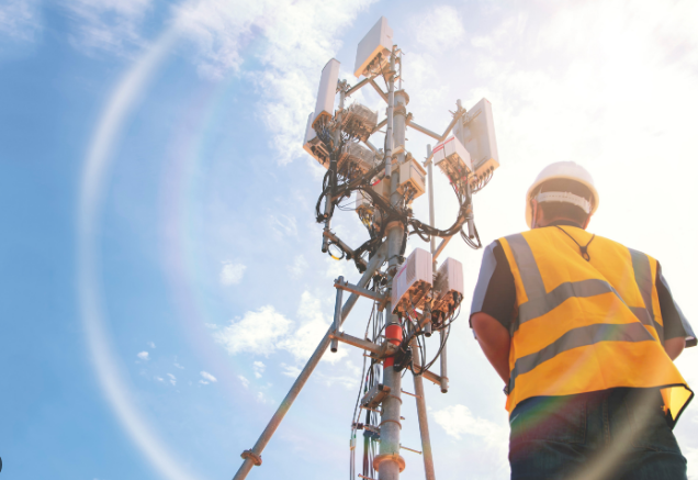
It therefore poses, in turn, one of the most significant challenges to radio wave communication: electromagnetic interference or EMI. Different electrical devices emit electromagnetic waves of frequencies that may interfere with radio communication signals. The sources of EMI vary from household appliances and cellular phones to complex machinery in industry; each of these sources has different effects on the radio signals depending on their proximity, power, and frequency. Understanding the effects of EMI and how to eliminate them is fairly relevant, especially in highly concentrated cities or industrial regions where sources of interference are common.
House appliances like microwaves, fluorescent lights, and even cordless phones add to EMI at home. The most notorious causes of interference in Wi-Fi networks using the same frequency are microwaves operating on an approximate 2.45 GHz. A typical microwave is able to create EMI levels strong enough to reduce the Wi-Fi signal strength by up to 20 dB within a range of 3 to 5 meters. This interference can cause marked dips in Internet speed and in the stability of one’s connection. To minimize this effect, one can place Wi-Fi routers and devices as far from microwaves as possible, and they should also run on different bands of frequency, such as 5 GHz instead of 2.4 GHz, to keep the signal clearer.
In industrial settings, EMI is even more pronounced due to heavy machinery and electrical equipment. The power level at which most industrial machinery operates is usually quite high and generates serious EMI in a wide range of frequencies. An electric motor, for example, used at an enterprise might radiate enough EMI to reduce radio signal strength by 30 dB or more within 10 meters of the motor, depending upon its power level and insulation. These extremely high-powered bursts of EMI come from welders, arc furnaces, and other high-energy equipment; they may cause extreme disruption to radio systems in their vicinity. Shielding equipment and installing EMI filters on sensitive devices can help reduce these disruptions in factories and other industrial settings.
In medical settings, EMI is a matter of paramount concern—particularly for sensitive devices such as MRI machines and heart monitors. The MRI, powered by high magnetic fields and radio waves, may radiate EMI that interferes with other devices within a radius of approximately 100 meters. It was estimated in one research that an MRI may degrade the signal about 40 dB in radio communication equipment operating over the same frequency range. To handle this, hospitals define certain EMI-free zones where the communication equipment and sensitive electronics are appropriately shielded or filtered to reduce interference. In addition, equipment in these zones is designed with strict EMI criteria in order not to interfere with safely treating a patient or with the proper working of life-supporting apparatus.
Solar Activity
Solar activities, especially over long distances and high altitudes, seriously affect radio wave propagation. Solar flares, sunspots, and solar winds disturb the ionosphere of Earth—a critical layer beyond which radio waves need to bounce back to the ground. These solar activities introduce fluctuations in ionospheric density and thereby have an impact on signal strength, clarity, and transmission range for various frequency bands; especially, HF radio communications are concerned, which is commonly used in aviation and maritime communications.
Solar flares, for example, release huge amounts of energy in the form of radiation, which reaches Earth in minutes. A solar flare interacting with the ionosphere can create a sudden ionospheric disturbance in the D-layer, which then starts absorbing HF radio waves between 3 MHz and 30 MHz. During strong solar flare events, HF signals may have losses of up to 20 dB, reducing transmission range by more than 50%, and global communications could be disrupted for several hours. In extreme cases, such flares cause a radio blackout at HF, where the signals are not usable for several hours on the sunlit side of the Earth. This becomes highly interfering, particularly in emergency and military communications which depend very much on the HF frequency range to achieve coverage over great distances.
Sunspots also affect radio wave propagation. Increasing sunspot activity during an approximate 11-year solar cycle strengthens the ionosphere to reflect HF signals, thereby giving a greater communication range at some frequencies. During periods of high sunspot activity, HF radio operators are afforded increased signal propagation, sometimes achieving “skip” distances of 2,500 miles on a single bounce. At the opposite end of the spectrum, when the sunspot activity is at its lowest ebb, HF signals lose some of this added propagation capability, with transmission range reduced by about 30%. In fact, this is why operators have noticed that signal degradation can drop the effective range of a 10 MHz signal by up to 500 miles during low sunspot phases versus peak sunspot phases.
Solar winds, similarly emitted by the sun, also have an effect on both the structure and the behavior of the ionosphere. Such solar winds immediately cause distortion in the geomagnetic field when approaching Earth and result in the auroral ionization of polar regions. This then develops unpredictable radio wave propagation. As a result, HF and VHF signals fade very rapidly, or even disappear completely. For instance, during strong solar wind storms, VHF signals (30 MHz to 300 MHz) are more strongly scattered by scintillation, causing 10-15 dB variations in a few minutes. The impact is strongest in polar regions and thus impacts flights relying on VHF communications and navigation systems because of losses as high as 40% in signal coherence during these disturbances.
Atmospheric Layers
These atmospheric layers are of great importance with respect to the behavior of radio waves, particularly in the propagation of radio waves over a long distance. Each has a different effect on the radio signal, depending on frequency and environmental conditions; namely, the troposphere, stratosphere, and ionosphere. This shall help in understanding the said effects and thereby managing and optimizing radio communication for particular applications such as broadcasting, aviation, and marine navigation.
The troposphere is the lowest layer of the atmosphere. This layer greatly influences both the VHF and UHF frequencies, which are utilized in TV, radio, and cellular communication. Tropospheric ducting is the bending of radio waves due to the refractive effects of temperature and humidity gradients in this layer. Under conditions of high humidity and temperature inversion—when a layer of warm air overlays an area of cooler air—VHF signals can travel well beyond the normal line-of-sight horizon, extending as much as 500 km compared to the usual 50-100 km range. On the other hand, this ducting may also cause interference between distant stations on the same frequency due to the overlap and deterioration of signals during changes in weather. For instance, temperature inversion over sea areas may interfere with radio or TV stations from a large distance, which affects the quality of reception for local broadcasts.
Above the troposphere, the stratosphere does not have significant direct effects on most radio frequencies since it lacks dense gas and particulate matter needed for the reflection and refraction of signals. Contribute indirectly to this tropospheric ducting event, however, by adding to the temperature inversion layers at its boundary with the troposphere. There is, however, little or no direct impact of the stratosphere on radio signals, even though at abnormal temperature conditions, radio signals, particularly in the VHF and UHF frequencies, will suffer slight refraction while passing through this layer, but these effects are minor compared to those in the troposphere. Under nominal conditions, a VHF signal at 150 MHz would suffer only about a 1–2 dB negligible loss as it passed through the stratosphere.
Above the stratosphere, the ionosphere most distinctly affects radio wave propagation for frequencies in the HF range, 3–30 MHz. This layer is made of layers of ionized particles whose density varies day to night due to the ultraviolet radiation from the sun. During daytime, HF waves get absorbed in the D-layer of the ionosphere, which causes signal attenuation; hence, reduction in the strength of the signal, sometimes up to 20 dB, and this affects frequencies mostly below 10 MHz. At night, this D-layer dissipates, and HF signals can reflect from the higher F-layer, giving long-distance propagation over several thousands of kilometers. This sort of propagation is known as skywave propagation and forms the basis of international broadcasting and amateur radio. However, ionospheric density is subject to highly variable changes, in particular due to solar activity. At times of solar maximum, ionospheric disturbances may degrade the clarity of HF signals by as much as 30% or more, rendering dependable long-range communication unreliable.
Multi-path Interference
Multi-path interference is the effect which remarkably destroys radio wave transmission in an urban or indoor environment, where the signal sees all sorts of reflective planes. That is to say, a radio wave signal takes various paths to reach a receiver by reflection, scattering, and diffraction by buildings, vehicles, and other objects. These signals can reach the receiver at slightly different times and thus may cause constructive or destructive interference that can affect the quality of the total signal. Basically, to have radio communication management, it is important to understand what multi-path interference is and its several impacts.
Due to a great concentration of reflective structures such as buildings, glass windows, and metallic surfaces, multi-path interference can occur easily in cities. For instance, tall buildings in city centers can reflect a 100-MHz FM radio signal by dispersing the signal delays by as much as 5 microseconds. This causes what is referred to as a fluctuation in received signal strength by as much as 20 dB over very short distances of just a few meters. Moreover, vehicles in highways introduce relative moving reflective surfaces adding to interference and making radio reception for mobile users less predictable. The resulting signal degradation is particularly high in regions with heavy congestion of buildings where up to 50% of the original signal strength may be lost due to multi-path effects.
Indoors, the multi-path interference may seriously affect the signal-to-noise ratio of both Wi-Fi and Bluetooth, especially in working, shopping, or home environments that are rich in reflective or absorbing materials. A Wi-Fi signal operating in the 2.4 or 5 GHz bands, for example, may reflect from walls, floors, and ceilings before it reaches a device down a number of different paths. When these signals come together, they can reinforce each other or completely cancel each other out and cause signal fluctuations, better known as “fading.” For example, in office scenarios, the Wi-Fi signal strength could vary as much as 15 dB with device position relating to reflective surfaces. These fluctuations can cut internet speeds up to 30% and make video calls and streaming services unreliable. Multiple antenna routers, often with “MIMO” or multi-input, multi-output technology, are designed to process several paths at once in order to minimize the multi-path interference in those scenarios.
Multi-path interference poses a special problem in aviation and marine navigation because the signal skitters across multiple surfaces—on the ground, the water, and even on the skin of the airplane or vessel. In aircraft, GPS signals at 1.575 GHz and 1.227 GHz are specifically prone to multi-path interference, with reflections from the plane fuselage and wings. These multi-path reflections can bring positioning errors to as high as 10 meters and, in certain situations, are critical for their precision navigation. Such effects are combated by employing advanced GPS receivers with appropriate algorithms that filter out the delayed signals due to multi-path interference on many aircraft. Moreover, pilots are trained to use multiple navigation systems to cross-check positions, thereby reducing dependence on any one system that might be interfered with.
Frequency Bands
Frequency bands are most important in their potential to determine how radio waves can behave about their environment: propagating distance, interference susceptibility, and obstacle penetration. Different ranges of frequency act differently in response to the same environmental conditions; hence, for certain applications, some frequency bands are more suitable than others. Knowing how frequency bands affect the nature of radio waves can thus help us optimally select frequencies for applications in broadcasting, communication, and data transmission.
The low-frequency band stretches from 30 kHz to 300 kHz and, due to low absorption by atmospheric conditions, is highly capable of long-distance propagation. LF waves can travel as far as 2,000 kilometers while following the Earth’s surface—a kind of propagation known as ground wave propagation. For example, the LF band is employed for navigational systems and maritime communication because its long wavelength easily passes through water and reaches over enormous distances without much interference. On the other hand, to transmit LF waves, it needs very huge antennas of the size of several hundred meters. This restricts the use of LF in many practical applications. Besides, while insensitive to physical blockages, LF waves have limited data-carrying capability and hence are unsuitable for modern high-speed data applications.
In the HF band, 3–30 MHz, signals can reach very long distances of up to thousands of kilometers because of reflections from the ionosphere, allowing “skywave” communication. For international broadcast, amateur radio, and military communications, HF band is suitable. By contrast, HF signals are readily subject to the action of the atmosphere, which in turn is nearly controlled by the diel cycle. During the daytime, the D-layer of the ionosphere absorbs HF signals under 10 MHz; sometimes this reduces the effective range by half when compared to nighttime conditions. During nighttime, when the D-layer breaks up, these frequencies can go further, as they reflect off the higher F-layer. However, this HF band is vulnerable to solar activity; for example, during a solar flare, it can degrade HF signal clarity by up to 70% in just a few hours. Because of this, long-distance communications cannot be relied upon.
The VHF band falls between 30 to 300 MHz, and finds its application in FM radio, television broadcasts, and two-way communication systems. Because VHF waves travel principally by line-of-sight—with limited diffraction around obstacles—their effective range is restricted to about 50-100 kilometers, depending on the height of the transmitter. Thus, buildings and hills form a block to the VHF signals. The effectiveness of this band is less in urban areas. However, the VHF band provides an excellent trade-off between range and quality, with relatively little interference from environmental noise compared to lower bands. FM radio, for example, broadcasts between 88 and 108 MHz and provides high quality audio to up to an 80-kilometer radius from the transmitter. An unusual atmospheric condition called tropospheric ducting can forward VHF signals hundreds of kilometers beyond the horizon for short periods of time, and from time to time FM stations can be received at great distances, but this effect cannot be depended upon.
The ultra-high frequency band, 300 MHz–3 GHz, is used for broadcasting television, for cellular phones and for Wi-Fi. Its wavelength is so much smaller than that of AM radio or FM radio signals that it’s well-suited for carrying substantial amounts of data—which it does in applications like video transmission and high-speed internet access. On the downside, UHF signals have limited range and are more subject to physical barriers than longer-wavelength radio waves. For example, a 900 MHz UHF signal utilized in mobile communication could be attenuated as much as 20 dB for passing via a concrete wall; this accordingly reduces effective indoor coverage. Atmospheric absorption within the UHF band is higher, most in humid conditions, and can reduce the signal by about 1 to 2 dB every kilometer in high-humidity conditions. Despite these limitations, UHF frequencies are in wide use in urban areas due to their high data capacity and matching with compact antennas suitable for portable devices.

