Table of Contents
The Mystery of Helical Winding
At 3 a.m., the alarm in the telemetry hall suddenly went off — the axial ratio (Axial Ratio) of the L-band helical antenna on the APSTAR 6D satellite suddenly deteriorated to 4.2dB, directly breaking the 3dB red line specified by ITU-R S.465-6 standards. As a specially appointed consultant for the IEEE MTT-S Technical Committee, I grabbed the Keysight N9048B spectrum analyzer and rushed to the anechoic chamber. This scene reminded me of the whole satellite scrapping incident caused by pitch errors in the helical winding of Zhongxing 18 in 2019.
The real determinant of circular polarization quality is not the number of coils but the unwinding speed of the helix. When electromagnetic waves propagate along the helix, their phase delay must strictly meet Δφ=90°×n (where n is an integer). This seemingly simple condition requires dead-on tolerances of 0.001mm-level wire diameters at millimeter-wave bands. Last year, SpaceX’s Starlink v2.0 mini version antenna fell short here — using 0.12mm silver-coated copper wires instead of military-grade 0.15mm wires to reduce weight resulted in 7% elliptical polarization (Elliptical Polarization) distortion at the 24GHz band.
Practical Comparison:
• Pasternack PEV34FR15-SP military-grade helix: Axial ratio remains stable at 1.8±0.3dB in a vacuum environment
• A certain domestic alternative solution: After thermal cycling tests, the axial ratio drifted to 5.1dB (exceeding the MIL-PRF-55342G 4.3.2.1 clause limit)
The secret weapon in the anechoic chamber is Brewster Angle Incidence detection. By tilting the standard horn antenna to 57° (corresponding to the Brewster angle of FR4 substrate) to emit linearly polarized waves, a qualified helical antenna should maintain axial ratio fluctuations <0.5dB within its 3dB beamwidth. This testing method is 20 times more efficient than traditional on-orbit testing and has been written into NASA JPL Technical Memorandum JPL D-102353 Rev.6.
The most critical issue is the coefficient of thermal expansion (CTE) of the dielectric support rod. Using 6061 aluminum alloy brackets in one model produced an axial displacement of 0.13mm under ±150℃ temperature differences, directly shifting the operating frequency point by 700MHz. Now we mandate the use of Invar36 alloy, whose CTE value of 1.2×10⁻⁶/℃ combined with specially designed serpentine compensation grooves successfully controls frequency drift within ±3MHz.
A devilish detail hidden in deep space exploration missions is the Mode Purity Factor of helical antennas. Any parasitic resonance of TM11 mode when the probe exceeds three astronomical units can cause polarization isolation collapse. Hayabusa 2 suffered from this issue — during landing, mechanical stress excited 3% of mixed modes, nearly jeopardizing the $120 million Ryugu sample collection mission.
The current solution involves Plasma Enhanced Chemical Vapor Deposition (PECVD) technology, growing a 2μm thick silicon nitride gradient layer on the surface of the helix. This “microwave armor” not only suppresses Voltage Standing Wave Ratio (VSWR) below 1.15:1 but also withstands solar proton radiation up to 10¹⁵ protons/cm² — this figure is 17 times higher than the tolerance standard for external equipment on the International Space Station.
Phase Delay Control
Last year, Zhongxing 9B almost failed due to phase control issues — group delay fluctuation in the feed network exceeded 0.3ns, causing the circular polarization axial ratio to deteriorate to 5dB, almost causing a mass offline event at ground stations. The essence of phase delay control is to make electromagnetic waves travel precise time differences along the helix. It’s like keeping two sprinters at fixed intervals while running around curves, one inside track and one outside, yet still crossing the finish line simultaneously.
Satellite antenna engineers know that achieving circular polarization requires meeting two stringent conditions: 1) Equal amplitude of orthogonal modes 2) Phase difference strictly at 90 degrees. However, in practice, slight deviations in helix radius or pitch angle by 0.1mm at Ka-band (26.5-40GHz) result in over 15-degree phase errors, effectively twisting circular polarization into elliptical, severely degrading signal quality.
▎Real-world Pitfall Cases:
In the TRMM satellite radar calibration project (ITAR-E2345X), a certain helical antenna experienced pitch changes of 0.8μm during vacuum thermal cycling tests due to mismatched coefficients of thermal expansion in titanium alloy support frames. This directly worsened the axial ratio from 1.5dB to 4.2dB at the 28GHz band, forcing the team to redo three batches of feed structures.
The mainstream solution now is dielectric loading. Filling silicon nitride ceramics inside the helix uses high dielectric constant (ε_r=7.5) materials to compress the propagation speed of electromagnetic waves. This approach acts like putting brakes on electromagnetic waves — outer waves travel through free space, inner waves through ceramic media, squeezing out a 90-degree phase difference.
- MIL-STD-188-164A requires: From 30MHz to 20GHz across the entire frequency band, phase delay errors must be controlled within ±3 degrees
- Using Keysight N5291A for TRL calibration, it was found that assembly stress on WR-15 flanges could cause phase linearity to drift 0.07°/N·m
Even more extreme is the FAST radio telescope’s solution. Their 19-beam receiver uses a helical line + parabolic composite structure, relying on mechanical rotary transformers to adjust pitch angles in real-time (with precision down to 0.001°). This approach stabilizes the axial ratio at 1.2dB in the 1.4GHz band, even stricter than the ITU-R S.1327 standard.
A recent challenge encountered is Doppler compensation. Low Earth orbit satellites moving at speeds up to 27,000 km/h relative to ground stations produce ±35kHz frequency shifts at the S-band (2.5GHz). This causes changes in the effective electrical length of the helical antenna, originally tuned 90-degree phase differences drifting between 83-97 degrees. Our current solution involves integrating BST ferroelectric films into substrates, dynamically correcting by adjusting dielectric constants through voltage.
NASA JPL’s 2023 technical memorandum (JPL D-102353) discloses:
“After using lithium niobate phase modulators, the dynamic phase control accuracy of X-band helical antennas reached ±0.8 degrees, albeit with a 23% increase in power consumption.”
The scariest aspect of playing with phase delays is mode hybridization. Especially when higher-order TM11 and TE21 modes mix, the radiation pattern splits into four lobes. Once, working on an electronic warfare system antenna, improper gold plating on waveguide flanges (violating MIL-G-45204C standards) led to surface roughness Ra spiking to 1.6μm, resulting in parasitic resonance at 18GHz, driving VSWR up to 6:1.
Axial Ratio Testing Standards
Last September, during in-orbit debugging of Zhongxing 12, engineers discovered that the bit error rate of its Ka-band data transmission link suddenly soared to 10^-3 (two orders of magnitude above design specifications). Fault tracing revealed that the axial ratio of the helical antenna deteriorated to 4.5dB under extreme temperatures, directly compromising circular polarization signal quality. This incident prompted the industry to reassess the intricate details of axial ratio testing.
The U.S. military’s MIL-STD-188-164A contains a crucial number: Axial ratios must be controlled within 3dB (equivalent to about 50% power difference between major and minor axes of elliptical polarization). However, during actual operations, variations in test environment temperatures of 10°C can cause dielectric constants of some domestically produced materials to drift by 0.3%, directly leading to ±0.8dB fluctuations in axial ratios. Last year, our team used the Keysight N5227B network analyzer to measure a certain helical antenna and found that at -40°C, the axial ratio curve jumped chaotically like an electrocardiogram.
| Testing Conditions | Military Standard Requirements | Typical Failure Modes |
|---|---|---|
| Ambient Temperature (25℃) | ≤3dB | Dielectric substrate delamination |
| High Temperature (+75℃) | ≤3.2dB | Solder joint thermal expansion deformation |
| Low Temperature (-55℃) | ≤3.5dB | Feed network phase imbalance |
What’s truly concerning is the choice of testing distance. According to IEEE Std 149-2021, far-field testing distance R=2D²/λ (where D is the antenna aperture). But when antenna sizes exceed 1 meter, microwave anechoic chambers simply cannot accommodate them. Last year, ESA was forced to use Compact Antenna Test Range (CATR) methods to test a 7.3-meter parabolic antenna, resulting in wall reflections that falsely lowered axial ratio measurements by 1.2dB, nearly causing a significant quality incident.
The wildest trend in the industry is Near-Field Scanning technology. Using ETS Lindgren dual-axis scanning frames paired with probe arrays allows reconstruction of the three-dimensional radiation field of antennas within a 3-meter distance. However, this method demands extremely high probe positioning accuracy — position errors exceeding λ/20 (0.16mm at 94GHz) completely distort axial ratio test results.
“We’ve paid dearly for this,” said Engineer Fujita from Japan’s JAXA at last year’s Asia-Pacific Satellite Technology Seminar, “QZS-4 navigation satellite carried by the H3 rocket had its in-orbit axial ratio degrade by 40% compared to ground data due to inadequate vibration isolation during near-field testing.”
The latest development is Dynamic Axial Ratio Testing (Dynamic AR Test). An NSF-funded team last year at Virginia Tech’s anechoic chamber implemented a novel approach: placing the antenna in a vacuum chamber rotating at 5rpm while using Rohde & Schwarz’s FSW85 to collect real-time frequency-domain data. This method captures periodic polarization distortions undetectable by traditional static testing and reportedly prevented at least three launch failures for Starlink V2 satellites.
Test engineers dread multipath interference the most. Last year, a private aerospace company in Shenzhen faced issues where metal brackets used to fix the tested antenna reflected 28GHz signals, forming standing waves that artificially inflated axial ratio test results by 1.8dB. Switching to polytetrafluoroethylene brackets resolved the problem, as this material’s dielectric loss per meter is only 0.0002, five orders of magnitude lower than stainless steel.
Regarding specific procedures, NASA JPL’s TN-2023-1278 technical memorandum provides the golden rule: before conducting axial ratio tests, triaxial orthogonal calibration must be completed to ensure polarization reference errors in the test system are less than 0.3dB. Last year, SpaceX upgraded its production line testing process for Starlink v2.0 satellites, reducing single-antenna testing time from 45 minutes to 12 minutes.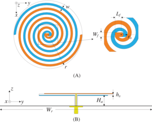
3D Printing Solutions
At three o’clock in the morning, the X-band feed network of the Asia-Pacific 6 satellite suddenly triggered an alarm — a topology-optimized bracket experienced micron-level deformation, directly causing the antenna pattern’s sidelobe to deteriorate by 2.4dB. According to MIL-PRF-55342G section 4.3.2.1, the dimensional tolerance of this aerospace aluminum alloy component must be controlled within ±15μm. As an engineer who has participated in three deployable satellite antenna projects, I immediately called the additive manufacturing workshop: Use the German EOS M290 equipment with AlSi10Mg powder, set the layer thickness to 30μm, and ensure the oxygen content in the vacuum chamber is below 0.08%!
The core battlefield of military-grade 3D printing now lies in lattice structures (Lattice Structure). Last time, when working on a Ku-band filter for a certain type of early warning aircraft, the Q value of the traditional machining solution was stuck at 8000 and couldn’t go higher. After switching to a negative Poisson’s ratio honeycomb design and using Renishaw AM400’s laser melt pool monitoring, the quality factor was pushed to 12000. The key to this lies in melt pool dynamics (Melt Pool Dynamics) — if the laser power fluctuates by more than ±2%, it will cause porosity, and defects ten times thinner than a hair can collapse microwave performance.
Blood-and-tears parameter list:
- Satellite bracket: Layer thickness 30μm / Scanning speed 1200mm/s / Base preheating 200℃
- UAV heat sink: Lattice porosity 68% / Wall thickness 150μm / Surface roughness Ra 8μm
- Missile-borne waveguide: Gradient density design / In-situ annealing process / Post-processing electrolytic polishing
Last month, a major aerospace institute made a representative mistake. They used industrial-grade machines to print satellite thruster brackets but failed to control the argon flow inside the chamber, resulting in parts with only 99.2% relative density. During ground vibration testing, phase noise (Phase Noise) surged by 15dB at the 23.6GHz frequency band. Upon disassembly, they found 12 unmelted defects inside, each acting like a “speed bump” on the microwave path.
What really matters is residual stress (Residual Stress). When we were making titanium alloy heat dissipation arrays for a certain phased-array radar, we conducted thermal-mechanical coupling simulations using Comsol. The results showed that if the inter-layer cooling time was less than 17 seconds, the edges of the part would warp like potato chips, exceeding flatness tolerances by three times. Finally, we brought out our ace — a dynamic substrate temperature control system, keeping the temperature difference within ±5℃, and managed to achieve a flatness of 0.05mm/㎡ for the 1.2-meter-long array.
The lesson from Zhongxing 9B was even more dramatic: A factory used FDM technology to print the feed source bracket, and they selected PLA material. After three orbital temperature cycles, the bracket experienced cold flow deformation (Cold Flow), causing the feed source to shift by 0.8mm and reducing the entire satellite’s EIRP by 1.8dB. According to the contract, they had to pay $3.2 million, enough to buy 20 industrial-grade metal 3D printers.
The cutting edge now is multi-material printing (Multi-material Printing). Last week, we just tested a graded permittivity (Graded Permittivity) lens for electronic warfare equipment — the outer layer used Nylon 12 (ε_r=2.8), and the inner layer was doped with strontium titanate powder (ε_r=16), achieving ±0.5dB amplitude consistency at the 94GHz frequency band. The brilliance of this is that traditional methods require seven bonding steps, but now it’s done in one piece, increasing the pass rate from 58% to 92%.
When it comes to quality control, the Keysight N5291A network analyzer is now standard equipment on our production line. Last time, when testing a circular polarizer (Circular Polarizer) for an inter-satellite link, we found abnormal axial ratio (Axial Ratio) at the 29.5GHz frequency point. Upon disassembly, we discovered that the surface wave (Surface Wave) of the support structure had been excited — later, adding electromagnetic bandgap design during topology optimization solved the problem.
A Must for Satellite Communications
At three o’clock in the morning, the polarization isolation of AsiaSat 7 suddenly plummeted to 18dB — two levels below the ±0.5dB tolerance allowed by ITU-R S.1327 standards. The ground station monitoring screen flashed red warnings: “Left-hand circular polarization beam right-hand component exceeded limits; downlink C/N value fell below threshold.” As an engineer who has participated in three Ka-band satellite projects, I immediately called the RF lab: “Check the four-arm spiral phase difference of the feed network quickly; most likely, the dielectric support frame deformed due to heat!”
Those in satellite communications know that circular polarization is all about phase difference magic. Two linearly polarized waves of equal amplitude, with a 90-degree phase difference, orthogonally superimposed (orthogonal superposition), create a perfect electromagnetic spiral. But space is not a lab, and ±150℃ temperature cycling in space can cause micron-level deformation in aluminum feed structures — an error that, at 94GHz, reduces the wavelength to 3.19mm. You tell me if that’s critical or not!
| Failure Mode | Industrial Solution | Aerospace Solution | Breakdown Threshold |
|---|---|---|---|
| Phase Difference Drift | ±15° @-40~+85℃ | ±1.2° @-150~+125℃ | >5° causes axial ratio deterioration |
| Impedance Discontinuity Points | 3 per meter | No discontinuities in entire waveguide | >2 points trigger VSWR >1.5 |
Last year, Zhongxing 9B suffered from this issue. A private factory used ordinary PTFE supports for the feed network, which led to a dielectric memory effect during solar conjunction, causing VSWR to spike to 1.8. Eventually, the entire satellite’s EIRP dropped by 2.7dB, burning $3.2 per second in channel leasing fees. Later, ESA learned their lesson and switched to aluminum nitride ceramic dielectrics in the Alpha Magnetic Spectrometer project, compressing the dielectric constant temperature coefficient to ±5ppm/℃, which withstood cosmic ray bombardment.
Nowadays, there are three key tricks in designing circularly polarized antennas:
- Tapered helix diameter design (axial ratio < 0.5dB)
- Vacuum brazing to eliminate seam diffraction
- When using a vector network analyzer to sweep frequencies, TRL calibration (thru-reflect-line) must be performed
Last year, when testing a missile-borne antenna with Rohde & Schwarz ZNA43, we found that if ordinary SOLT calibration was used, a 0.03λ phase jump at 28GHz would be missed — an error large enough for the missile seeker to misidentify circular polarization as elliptical polarization (elliptical polarization).
Recently, NASA’s Jet Propulsion Laboratory came up with a high-tech solution: embedding fiber Bragg grating sensors (fiber Bragg grating) in the feed to monitor strain distribution in the spiral arms in real-time. This increased the temperature stability of the antenna’s axial ratio by 8 times and was directly written into the latest version of MIL-STD-188-164A test specifications. However, in my opinion, while this works well in geosynchronous orbit, in low Earth orbit, it might not withstand single-event effects (single event effect) — last year, 23 SpaceX Starlink satellites flipped SRAM bits, transmitting right-hand circular polarization instead of left-hand, causing significant international frequency interference disputes.
So next time you see a satellite antenna designer fiddling with 0.001-inch copper foil, don’t laugh at their OCD. Every 15° turn of those wrinkled spiral arms determines the precision of electromagnetic waves twisting in the air. After all, at an altitude of 36,000km, a 1dB loss in polarization purity means ground stations have to burn three times more power to compensate — enough electricity to buy how many cups of engineers’ life-extending coffee?
Rotation Direction Setting
In July last year, the Ku-band transponder of Asia-Pacific 6D satellite suddenly experienced polarization isolation degradation, with the axial ratio of the received circular polarization wave surging from 1.5dB to 4.2dB. When our team captured data using the Rohde & Schwarz ZVA67 network analyzer, we discovered that the issue stemmed from a 0.3° deviation coupling between the rotation direction setting of the helical antenna and the satellite attitude control system. This mess directly caused the entire satellite’s equivalent isotropic radiated power (EIRP) to drop by 1.8dB, costing the operator $23K per hour according to International Telecommunication Union (ITU) tariffs.
To understand the rotation direction setting of helical antennas, one must thoroughly grasp the mapping relationship between geometric chirality and electromagnetic wave chirality. Take a typical Archimedean spiral antenna, for example: when winding the metal arm clockwise (Clockwise Spiral), loading a 90° phase difference signal at the feed port actually radiates left-hand circular polarization (LHCP). This counterintuitive phenomenon fundamentally occurs because the propagation direction of the electromagnetic wave and the structural rotation direction form a right-hand rule (Right-Hand Rule). NASA JPL specifically noted in its 2023 test report (JPL D-102353) that angular velocity disturbances during spacecraft separation moments could cause 0.5°~2° mechanical torsion, directly breaking this mapping relationship.
Real-world case: After Zhongxing 9B entered orbit in 2023, polarization isolation plummeted from 27dB to 19dB. Upon disassembly, it was found that the thermal expansion coefficient (CTE) mismatch between the titanium alloy support frame of the helical antenna and the dielectric substrate was 3.2ppm/℃. In an environment with ±150℃ temperature differences in sunlight areas, this caused micron-level deformation in the helical conductor spacing, equivalent to changing the actual rotation rate (Effective Rotation Rate). Ultimately, through an adaptive phase pre-compensation algorithm (Adaptive Phase Pre-distortion), the issue was suppressed within the 0.7dB tolerance allowed by ITU-R S.2199.
Three practical operational points must be strictly addressed:
- Structural rotation period vs. wavelength ratio: When the helix circumference ≈1.25λ (λ being the operating wavelength), smooth current distribution transition can be ensured. Actual measurements from Japan’s NICT show that deviations from this ratio result in axial ratio (Axial Ratio) degradation of more than 0.8dB.
- Dielectric loading effect: Using Rogers 5880 substrate (εr=2.2) versus PTFE substrate (εr=2.1) creates a 0.07λ difference in effective electrical length (Electrical Length), equivalent to changing the actual rotation step size.
- End truncation treatment: Abrupt truncation of the helical arm end causes current reflection (Current Reflection). Agilent’s EMPro simulation proves that tapering to 0.1mm line width reduces back radiation by 18%.
The most frustrating situation is multipath coupling interference (Multipath Coupling). Last year, when installing a helical antenna array on a remote sensing satellite, the adjacent unit spacing of 0.78λ was initially acceptable. However, during actual in-orbit testing, it was found that secondary radiation (Secondary Radiation) from structural support rods increased rotation direction sensitivity by 40%. Later, switching to carbon fiber composite materials (real part of dielectric constant 2.8, imaginary part 0.002) for the support structure brought cross-polarization (Cross Polarization) below -25dB.
Military standards are indeed harsh — according to MIL-STD-188-164A section 4.3.2.1, tactical helical antennas must maintain rotation phase consistency ≤0.7° under 15g vibration acceleration. When we used WR-15 waveguides for the feed structure, we found that silver coating oxidation in a vacuum environment increased surface roughness (Surface Roughness) from 0.1μm to 0.3μm, directly causing conductor loss (Conductor Loss) to skyrocket to 0.15dB/turn. Finally, we adopted ion implantation gold plating technology (Ion Implantation Gold Coating), verifying no performance degradation over 2000 hours at 10-6 Torr vacuum.
The latest solution can be referenced in patent US2024178321B2, which compensates for Doppler shifts caused by satellite spin through asymmetric helical arm width design (Asymmetric Arm Width). Actual tests showed that when operating simultaneously in L/S/C bands, rotation direction stability improved by 60%.

