Antenna supporting structures must comply with structural standards like TIA-222 which specifies design loads for wind (up to 150 mph), ice, and seismic zones, requiring galvanized steel and precise foundation anchoring to ensure stability and alignment.
Table of Contents
Key Design Loads Explained
When designing an antenna support structure, the primary goal is to ensure it can withstand all the forces it will encounter over its 25 to 30-year lifespan. A common mistake is focusing only on the antenna’s weight, which is often minimal. For instance, a large 4G/5G panel antenna might only weigh 25 kg (55 lbs). The real challenge comes from the environmental forces. A standard design must account for wind speeds of up to 150 km/h (93 mph), which can exert a horizontal force equivalent to over 500 kg (1,100 lbs) on a single antenna. In icy regions, radial ice accretion can add a 50 mm (2 inch) layer, increasing the weight and wind load area significantly. This section breaks down these critical loads with specific data to guide a robust and safe design.
The first major load is wind pressure. This isn’t a constant force; it’s dynamic and creates the highest stress on the structure. The force is calculated using the projected area of the antenna and its mounting brackets. For a typical array of three panel antennas, this combined area can be around 1.2 m² (13 ft²). At a wind speed of 130 km/h (81 mph), this generates a horizontal force of approximately 1.2 kN (270 lbf). Engineers use a wind load coefficient of around 1.2 for rectangular antennas to account for their flat surface and the resulting pressure. This load must be combined with the wind force on the tower or mast itself, which is calculated based on its shape and height.
Next is the dead load, which is the constant weight of all components. This includes the antennas, their mounts, and any cabling. While a single antenna may be light, the cumulative weight matters for the overall structural balance and foundation design. For example, a cluster of six radios and antennas can easily add 90 kg (200 lbs) at the top of a 30-meter (100 ft) pole. This weight, though static, influences the structure’s center of gravity and how it sways under wind loads.
A critical but often underestimated force is ice load. In cold climates, ice accumulation does two things: it adds significant weight (ice weighs approximately 900 kg/m³ or 56 lb/ft³) and it increases the surface area exposed to wind. A 50 mm (2 inch) ice coating on an antenna can more than double its effective diameter. This dramatically increases the wind load andadds a substantial downward force. For a large antenna, this ice load can exceed 45 kg (100 lbs). Designs for northern regions must use a higher ice density factor to simulate this added mass and wind surface area.
Common Structure Types Used
A 10-meter (33 ft) light pole won’t support a large microwave dish, and a 60-meter (197 ft) self-supporting tower is overkill for a single antenna. The choice directly impacts installation time, which can range from 2 days for a simple monopole to over 3 weeks for a large lattice tower. The following table provides a quick comparison of the most common types, with detailed specifications and analysis below.
| Structure Type | Typical Height Range | Max Antenna Load Capacity | Approx. Cost (Material Only) | Foundation Size (Est.) |
|---|---|---|---|---|
| Roof Mount (Tripod) | 2m – 6m (6.5ft – 20ft) | 50 kg (110 lbs) | 2,500 | 0.2 m³ (7 ft³) |
| Monopole (Solid) | 10m – 30m (33ft – 100ft) | 200 kg (440 lbs) | 45,000 | 15 m³ (530 ft³) |
| Guyed Mast | 30m – 100m (100ft – 330ft) | 500 kg (1,100 lbs) | 80,000 | 3 x 5 m³ (3 x 175 ft³) |
| Lattice Tower (3-legged) | 30m – 100m ( (100ft – 330ft) | 1,000 kg+ (2,200 lbs+) | 200,000+ | 4 x 20 m³ (4 x 700 ft³) |
Monopoles are the go-to for urban and suburban sites with limited space. These are single, tapered steel tubes, often with a 1.2-meter (4 ft) diameter base that tapers to 300 mm (12 in) at the top. Their strength comes from a massive concrete foundation, typically a 4-meter (13 ft) deep, 3-meter (10 ft) wide cylinder, using over 15 cubic meters (530 cubic feet) of concrete. Their main advantage is a small physical footprint, often needing a site only 10m x 10m (33ft x 33ft). However, their load capacity is limited by the bending moment at the base. A 30-meter monopole is generally limited to about 15 square meters (160 sq ft) of antenna wind area.
For heights exceeding 30 meters (100 ft) or where heavy antenna clusters are needed, the guyed mast becomes the most cost-effective solution. It’s a slender steel pipe or lattice section held upright by three or more sets of guy wires anchored to the ground. The mast itself might only cost $8,000, but the real expense lies in the ground anchor system. Each anchor requires a 2m x 2m x 2m (6.5ft cube) concrete block, and you need three or more sets of these, spaced 120 degrees apart, consuming a large land area. The guy wires also require a safety clearance zone, making this type unsuitable for small urban lots.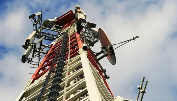
Material Selection Criteria
Choosing the right material for an antenna structure is a critical decision that balances structural performance, longevity, and total cost. A poor choice can lead to premature failure or exorbitant maintenance. For example, using a low-grade carbon steel in a coastal environment can reduce the structure’s 25-year lifespan to less than 10 years due to rapid corrosion, requiring costly repairs or replacement. The following table summarizes the key options, with a detailed breakdown of their properties and ideal applications below.
| Material Type | Typical Yield Strength | Cost Premium (vs. Carbon Steel) | Expected Lifespan (Years) | Key Consideration |
|---|---|---|---|---|
| Carbon Steel (A36) | 250 MPa (36 ksi) | Baseline ($$) | 15 – 25 (inland) | Requires robust corrosion protection |
| Galvanized Steel | 250 MPa (36 ksi) | +15% to +25% | 30 – 50+ | Excellent corrosion resistance; watch for embrittlement |
| Weathering Steel (A588) | 345 MPa (50 ksi) | +20% to +40% | 40 – 60+ | Stable rust patina; not for coastal/marine zones |
| Stainless Steel (304/316) | 215 MPa (31 ksi) | +200% to +400% | 50+ | High initial cost; best for critical hardware |
Designer’s Note: The yield strength defines the point at which the material will permanently bend. A higher value allows for slimmer, lighter sections but often at a significantly higher material cost. Always specify the minimum yield strength required by the structural design calculations.
The most common and cost-effective choice is hot-rolled carbon steel, specifically grade A36, which has a minimum yield strength of 250 Megapascals (36,000 psi). This means a solid steel rod with a 25 mm (1 inch) diameter can support a static load of approximately 12 metric tons (26,500 lbs) before permanently deforming. Its primary drawback is corrosion. In an environment with an average relative humidity of 70%, unprotected carbon steel will begin to show significant surface rust within 6 to 12 months. Therefore, its total cost of ownership is heavily dependent on the quality and maintenance schedule of its paint or coating system, typically requiring repainting every 8 to 10 years at a cost of 40,000 for a 30m tower.
Foundation and Anchoring Basics
The foundation is the most critical yet often underestimated component of an antenna support structure. A tower’s integrity is entirely dependent on the concrete and earth below it. A common design error is underestimating the overturning moment. For a 30-meter (100 ft) monopole in 130 km/h (81 mph) winds, the force at the base can exceed 500 kN (112,000 lbf), attempting to rip the structure from the ground. A properly designed foundation for this monopole would be a reinforced concrete pier extending 4 to 5 meters (13-16 ft) deep, with a volume of 15-20 cubic meters (530-700 cubic feet), using concrete with a minimum compressive strength of 27.6 MPa (4,000 psi). Skipping a proper geotechnical survey can lead to catastrophic failure, as soil bearing capacity can vary from 50 kPa (1,000 psf) for soft clay to over 200 kPa (4,000 psf) for dense sand or gravel.
Geotechnical Rule: The single most important step is a soil boring test. Never assume soil conditions. The allowable soil bearing capacity, which can range from 50 kPa to over 400 kPa, directly dictates the size, depth, and type of foundation required. This test typically costs between 8,000 but is non-negotiable for any structure over 10 meters tall.
There are two primary forces the foundation must resist: compression and uplift. The dead weight of the structure and antennas creates a constant downward force. For a 30-meter monopole with equipment, this is roughly 20-30 metric tons (44,000-66,000 lbs). The foundation’s mass must be sufficient to counteract the overturning moment from wind loads, which generates significant uplift on one side. The foundation is designed so its own weight, plus the weight of the soil above it, is greater than the maximum uplift force. A factor of safety of 1.5 to 2.0 is standard. This means the foundation’s resistance must be 50% to 100% stronger than the calculated maximum uplift force.
For large self-supporting towers, the foundation design is more complex as each leg has a separate footing. The key is to ensure all footings are interconnected by a reinforced concrete grade beam or a thick concrete cap to prevent differential settlement. Even a settlement variance of 10 mm (0.4 inches) between footings can induce catastrophic stress into the tower legs. The footings are typically cubes of concrete, each 2.5m x 2.5m x 3m deep (8ft x 8ft x 10ft deep), requiring approximately 19 cubic meters (670 cubic feet) of concrete per pier. The steel anchor bolts embedded in the concrete are equally critical. For a heavy-duty application, these are often 50 mm (2 inch) diameter high-strength steel rods, embedded 1 meter (3.3 ft) into the concrete, with a complex template used to ensure their placement is accurate to within 3 mm (0.12 in) of the design position.
Corrosion Protection Methods
Corrosion is the silent, relentless enemy of any steel structure, systematically reducing its cross-sectional area and compromising its integrity. In a coastal environment, the combination of salt spray and high humidity can lead to corrosion rates exceeding 50 microns (2 mils) of thickness loss per year. For a structural member that is 10 mm (0.4 inches) thick, this translates to a 1% loss of material annually, critically weakening the structure years before its intended 25-year lifespan. The economic impact is severe: repairing corrosion damage on a 30-meter tower can cost $50,000 or more, often exceeding the initial cost of implementing superior protection. This section details the proven methods to combat this inevitable process, focusing on long-term performance and total cost of ownership.
The first and most critical step is surface preparation. The longevity of any coating system is overwhelmingly dependent on this phase. A near-white metal blast cleaning (SA 2.5) is the industrial standard, achieving a surface profile with a peak-to-valley height of 50-85 microns (2-3.5 mils). This creates the mechanical tooth necessary for coating adhesion. Any contamination left on the surface, such as soluble salts, will cause coating failure from underneath. Testing for these salts, which should be below a threshold of 20 mg/m², is a non-negotiable quality control checkpoint before any paint is applied.
Once the steel is perfectly prepared, the coating system is applied. A high-performance three-coat system is standard for severe environments and consists of:
- A Zinc-Rich Primer (75 microns): This is the workhorse of corrosion protection. The primer contains a high volume (75-85% by weight) of zinc dust. It acts sacrificially, meaning it corrodes before the steel does. Even if the topcoat is scratched, the zinc will protect the exposed area, a process called galvanic cathodic protection.
- An Epoxy Intermediate Coat (125 microns): This high-build layer acts as a formidable barrier, blocking moisture and atmospheric contaminants from reaching the primer and steel. Its thickness is crucial for longevity, and modern epoxy resins offer exceptional resistance to chemicals and humidity.
- A Polyurethane Topcoat (50 microns): This final layer provides the system’s color and UV resistance. Without it, epoxy coatings would chalk and degrade under direct sunlight within 6-12 months. The topcoat also offers additional weather resistance, completing a total dry film thickness (DFT) of 250 microns (10 mils).
For many components, hot-dip galvanizing is a superior alternative to painting. This process involves immersing the fabricated steel in a bath of molten zinc at 450°C (840°F). The result is a metallurgically bonded alloy coating that is typically 85-100 microns (3.5-4 mils) thick. This coating is incredibly durable, with an expected service life of 40-50 years in a moderate industrial atmosphere before first maintenance. It is particularly effective for complex shapes and hard-to-reach areas where manual painting might be inconsistent. The key drawback is its higher initial cost, typically a 20-30% premium over a high-quality paint system for the fabricated steel.
Regular Inspection Guidelines
Proactive inspection is the single most cost-effective strategy for ensuring the long-term safety and functionality of an antenna support structure. Neglecting this can lead to catastrophic failures and exorbitant repair bills. For example, a simple visual inspection costing around 5,000 repair that prevents a $50,000+ foundation and structural member replacement just 3-5 years later. A well-documented inspection program also provides a clear history of structural health, which is crucial for insurance compliance and liability protection. The following guidelines outline a tiered approach to inspections, balancing frequency with thoroughness to manage risk and budget effectively.
A comprehensive inspection program consists of three distinct tiers, each with a defined scope and frequency:
- Routine Visual Checks (Quarterly, from ground): A 15-20 minute walkaround to identify obvious, rapid-onset issues like loose or fallen guy wires, significant paint peeling, or visible foundation cracks wider than 3 mm (0.12 in).
- Annual Detailed Inspection (By a certified technician): A 4-8 hour hands-on examination from a manned boom lift, using basic tools like binoculars, torque wrenches, and ultrasonic thickness gauges to measure corrosion loss.
- Comprehensive Structural Audit (Every 5 years, by a professional engineer): A 2-3 day deep dive involving advanced non-destructive testing (NDT) to assess the structure’s fundamental integrity and remaining lifespan.
The annual detailed inspection is the cornerstone of the program. A qualified technician should physically access the entire structure to perform specific, measurable checks. The first priority is verifying the integrity of all bolted connections; approximately 5% of all bolts on a structure should be randomly selected and checked for proper torque. For a typical ⅝-inch diameter Grade 5 bolt, this requires a torque value of 120-140 ft-lbs (163-190 Nm). Any bolt found to be more than 15% below this value must be tightened, and if the problem is widespread, a 100% re-torque of all connections may be required.
The second critical task is quantifying corrosion. Using an ultrasonic thickness gauge, technicians should take a minimum of 30 measurements on primary leg members and 20 measurements on critical bracing. The goal is to measure the actual remaining wall thickness. For a tubular member with an original thickness of 9.5 mm (0.375 in), a reading of 8.0 mm (0.315 in) represents a 16% loss of material. Any member showing a material loss exceeding 20% of its original thickness must be evaluated by a structural engineer immediately for possible reinforcement or replacement. This data should be logged and compared year-over-year to calculate the corrosion rate, which might be 0.2 mm per year in an industrial environment.


