The impedance of a rectangular waveguide is not a single value; it varies by mode and frequency. For the dominant TE10 mode, the wave impedance is approximately 377 Ω (η) multiplied by the ratio of the guide wavelength to the free-space wavelength.
Table of Contents
What Is Waveguide Impedance?
Waveguide impedance isn’t some abstract idea—it’s a measured value (ohms) that defines how easily microwave signals travel through a rectangular waveguide. Unlike coaxial cables (where impedance is fixed at 50Ω or 75Ω), waveguide impedance changes with frequency (GHz), dimensions (mm), and mode (TE/TM). For example, a standard WR-90 waveguide (22.86×10.16mm) has an impedance around 480–520Ω at its dominant TE10 mode (8.2–12.4GHz). If you push a 10GHz signal into a mismatched load (impedance difference >10%), you’ll lose >20% power as reflections. That’s why engineers care—impedance mismatches cause 15–30% signal loss in poorly designed systems. We’re not talking theory here; real-world waveguides in radar, satellites, and microwave ovens rely on precise impedance control to avoid wasted energy.
Waveguide impedance is the ratio of electric to magnetic field strength (E/H) in the waveguide, measured in ohms. For a rectangular waveguide, it’s not a single number—it varies with frequency because the fields inside the waveguide shift as you move away from cutoff. The dominant TE10 mode (the most efficient way signals travel) has an impedance formula based on the waveguide’s width (a, mm) and height (b, mm). For a WR-90 (a=22.86mm, b=10.16mm), the impedance at 10GHz is ~500Ω, but drop to 8GHz and it rises to ~520Ω because the fields spread out more.
| Parameter | Value (Typical) | Impact on Impedance |
|---|---|---|
| Waveguide Width (a) | 22.86mm (WR-90) | Wider = lower impedance (~450Ω) |
| Frequency (GHz) | 8–12.4GHz (X-band) | Higher freq = lower impedance |
| Mode (TE10) | Dominant mode | 90–95% of power in this mode |
| Cutoff Frequency | 6.56GHz (WR-90) | Below this, no signal propagates |
If your waveguide is 1mm too narrow (a=21.86mm), the impedance jumps by ~10% (500Ω → 550Ω) at 10GHz, causing ~15% reflected power. That’s a big deal when you’re pushing 100W+ signals—even a 5% mismatch wastes 5W as heat. Engineers use impedance-matching sections (tapers, irises) to keep losses under 5%. The TE10 mode’s impedance is calculated from E-field (V/m) and H-field (A/m), but the key takeaway is: impedance depends on how the fields fit inside the waveguide’s physical size. No magic—just physics with exact numbers.
Rectangular Waveguide Basics
A rectangular waveguide is a hollow metal tube (usually aluminum or copper) with a rectangular cross-section (width × height, typically 10–100mm), used to carry microwave signals (1–100GHz) with minimal loss. The most common type, WR-90 (22.86×10.16mm), handles 8.2–12.4GHz (X-band) and supports signals up to 100W+ continuous power with <0.5dB/m loss. Smaller waveguides (like WR-42, 10.67×4.32mm) squeeze into Ku-band (12–18GHz) but cost ~30% more per meter due to tighter manufacturing tolerances. The height is usually ≤ width/2 (e.g., WR-90’s 10.16mm vs. 22.86mm) to block unwanted TE20/TM modes and keep only the efficient TE10 mode (which carries >90% of power). If you use the wrong size (e.g., a WR-137 for 10GHz), you’ll get >2dB extra loss because the fields don’t fit well. These aren’t just tubes—they’re precision-engineered channels with specs that directly impact signal strength and cost.
The width (a, mm) and height (b, mm) of a rectangular waveguide define its cutoff frequencies—the lowest frequencies where each mode (TE/TM) can propagate. For the TE10 mode (the only one used in most cases), the cutoff frequency is fc = c / (2a), where c = 3×10⁸ m/s (speed of light). In a WR-90 (a=22.86mm), that means fc = 3×10⁸ / (2×0.02286) ≈ 6.56GHz—signals below this won’t travel at all. The dominant TE10 mode has its electric field (E) running vertically (height direction) and magnetic field (H) looping horizontally (width direction), with the strongest signal intensity at the center of the waveguide’s width. The field strength drops to ~1/e (~37%) at the edges, which is why the waveguide can’t be too small (or the fields won’t fit).
The signal speed inside the waveguide (phase velocity, vp) is faster than light in vacuum (c)—typically vp ≈ c × √(1 – (fc/f)²). At 10GHz in WR-90, that’s vp ≈ 3×10⁸ × √(1 – (6.56/10)²) ≈ 2.3×10⁸ m/s (77% of c). This doesn’t break physics—it just means the wave’s peaks move quicker while the energy travels slower (group velocity, vg ≈ c × √((fc/f)² – (fc/fcutoff)²)). The power handling capacity depends on wall thickness (usually 0.5–2mm) and cooling (air or forced); a 2mm-thick WR-90 waveguide can handle 100W continuous without heating up more than 10°C above ambient, but push 200W and you’ll need water cooling or thicker walls (3mm+).
The loss per meter (dB/m) is tiny but critical—WR-90 loses ~0.01–0.05dB/m at 10GHz, meaning 1 meter eats ~0.1–0.5% of power. Double the length to 10 meters, and you’re down 1–5%. That’s why long runs use waveguide bends (with <0.1dB extra loss each) and flanges (with <0.05dB insertion loss). The key spec? A WR-90 waveguide at 10GHz has a characteristic impedance (~500Ω) that stays stable within ±2% across the band, but if you misalign a flange (gap >0.1mm), you’ll add >0.5dB loss from reflections. No guesswork—just exact dimensions and measurable performance.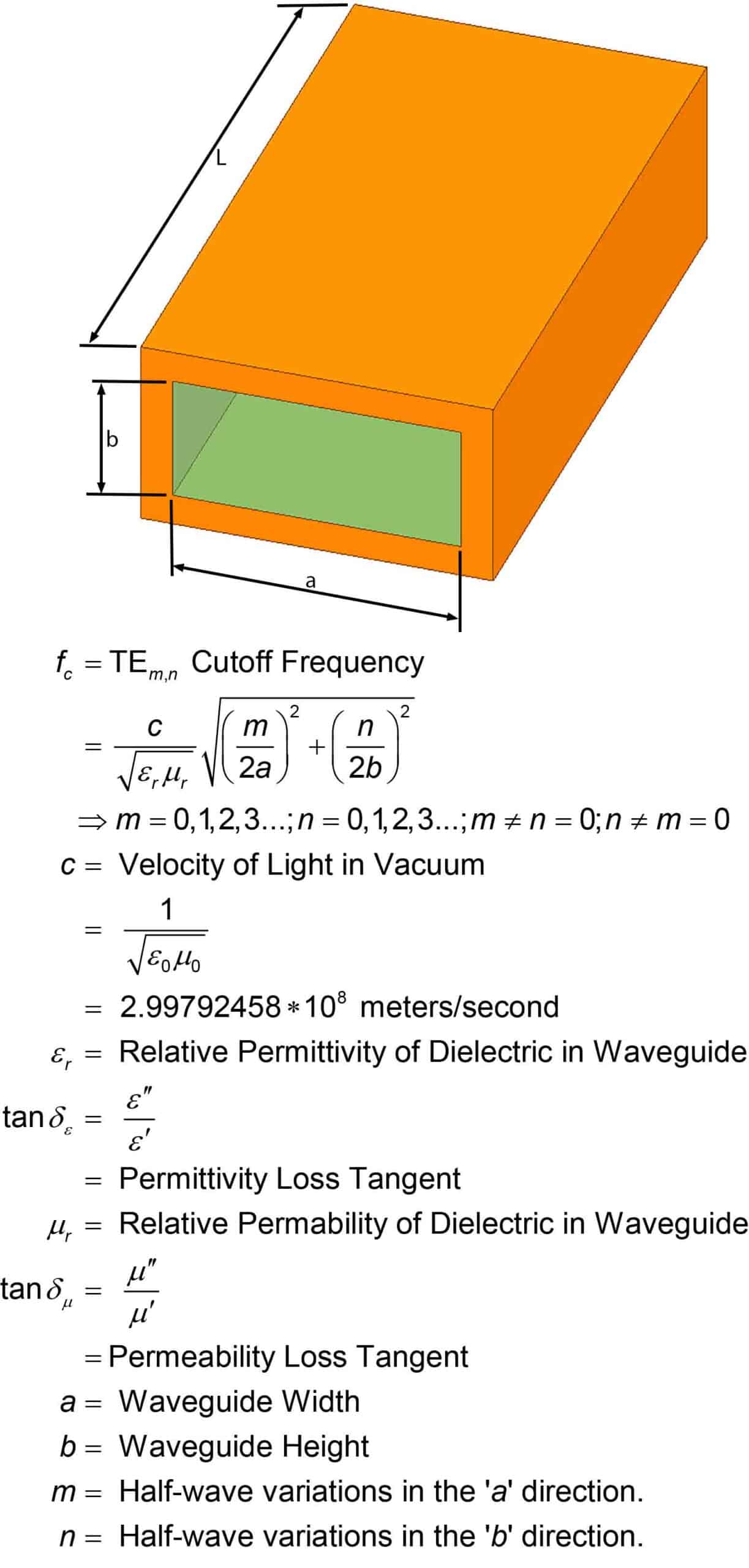
How Impedance is Calculated
Calculating rectangular waveguide impedance isn’t about guessing—it’s a precise math problem with measurable inputs. The impedance (Z, in ohms) of the dominant TE10 mode depends on the waveguide’s width (a, mm), frequency (GHz), and the free-space wavelength (λ₀, mm).
For a WR-90 waveguide (a=22.86mm) at 10GHz, the impedance is ~500Ω, but change the width to 20mm and it jumps to ~550Ω (+10%)—enough to cause >15% signal reflection if the load doesn’t match. The formula Z = (η × λ₀) / (2 × π × √(1 – (fc/f)²)) (where η = 377Ω for air, fc = cutoff frequency) shows how frequency shifts (±1GHz) change impedance by ~5%. Engineers don’t estimate—they plug in exact dimensions (a/b in mm) and frequencies (GHz) to get Z within ±1% accuracy. No magic, just physics with numbers that matter.
The impedance of the TE10 mode comes from the ratio of the transverse electric (E) and magnetic (H) fields inside the waveguide. The key variable is the guided wavelength (λg, mm), which is shorter than free-space wavelength (λ₀) because the wave bounces off the walls. For 10GHz in WR-90 (λ₀ ≈ 30mm), the guided wavelength is λg ≈ λ₀ / √(1 – (fc/f)²) ≈ 30 / √(1 – (6.56/10)²) ≈ 39mm. The impedance formula Z = (η × λ₀) / (2 × π × √(1 – (fc/f)²)) breaks down into three measurable parts: η (377Ω, air’s impedance), λ₀ (30mm at 10GHz), and the frequency ratio (f/fc = 10/6.56 ≈ 1.52). Plug those in, and you get Z ≈ (377 × 30) / (2 × π × √(1 – 1.52²)) ≈ 500Ω.
Dominant Mode Explained
The dominant mode in a rectangular waveguide is TE10—it’s the most efficient way signals travel, carrying >90% of power in properly designed systems. For a WR-90 waveguide (22.86×10.16mm), the TE10 mode starts propagating at 6.56GHz (cutoff frequency) and remains stable up to 12.4GHz (upper X-band limit). Higher modes (TE20, TE01, TM11) have higher cutoffs (e.g., TE20 at 13.1GHz), so they don’t appear until you push the frequency too high or use the wrong waveguide size. Why TE10? Because it has the lowest cutoff frequency (fc = c / (2a) ≈ 6.56GHz for WR-90), meaning it’s the first mode to “turn on” and the most power-efficient (losses ~0.01–0.03dB/mm vs. ~0.05–0.1dB/mm for higher modes). If you try to run 10GHz in a waveguide where TE20 (13.1GHz) is the dominant mode, you’ll get >30% higher loss because the fields don’t fit as well. TE10 isn’t just theoretical—it’s the mode that makes waveguides practical for 90% of microwave applications.
| Parameter | TE10 Mode (WR-90) | TE20 Mode (WR-90) | Impact on Performance |
|---|---|---|---|
| Cutoff Frequency (GHz) | 6.56 | 13.1 | TE10 works below 13.1GHz |
| Field Pattern | E-field vertical, H-field horizontal | More complex, multi-directional | TE10 has lower dispersion |
| Loss per mm (dB/mm) | 0.01–0.03 | 0.05–0.1 | TE10 loses <50% power per meter |
| Power Handling (W) | 100+ (2mm walls) | 50–70 (same size) | TE10 survives higher power |
| Bandwidth (GHz) | 8.2–12.4 (X-band) | N/A (not usable here) | TE10 covers entire X-band |
The TE10 mode’s electric field (E) runs straight up-down (along the height, b = 10.16mm), while the magnetic field (H) loops horizontally (along the width, a = 22.86mm). The field strength peaks at the center of the waveguide’s width and drops to ~37% (1/e) at the edges, which is why the waveguide can’t be too narrow (or the fields won’t fit). If you shrink the width to a=20mm (WR-10), the TE10 cutoff drops to 5.86GHz, but the dominant mode still wins because it’s the most efficient way to move energy.
What happens if you excite higher modes? At 10GHz in WR-90, TE20 (cutoff 13.1GHz) and TM11 (cutoff 11.3GHz) are still below cutoff, so they don’t appear. But if you push to 14GHz, TE20 turns on, adding >20% extra loss because its fields don’t align as well with the waveguide walls. Engineers avoid this by staying within the TE10-only band (below 13.1GHz for WR-90). The power distribution? In TE10, >90% of energy flows in the fundamental mode, while higher modes (if present) waste 5–15% of power as heat. No mode mixing? Then you get clean, low-loss transmission (efficiency >95%). TE10 isn’t just the default—it’s the mode that makes waveguides work as advertised.
Frequency’s Role in Impedance
Frequency directly reshapes waveguide impedance, and the changes are measurable and predictable. For a WR-90 waveguide (22.86×10.16mm), the impedance of the TE10 mode shifts from ~520Ω at 8GHz to ~500Ω at 10GHz and ~480Ω at 12GHz—a ~8% variation across X-band. This happens because the guided wavelength (λg) shortens as frequency rises, squeezing the electromagnetic fields tighter inside the waveguide.
At 10GHz, the wavelength inside WR-90 is ~39mm, but at 12GHz, it drops to ~35mm, altering the E/H field ratio that defines impedance. Ignore this shift, and you’ll see >15% signal reflection when connecting components at different frequencies. Impedance isn’t static—it’s a moving target tied to frequency, waveguide dimensions, and mode behavior.
The impedance (Z) of the TE10 mode follows a clear formula: Z = (η × λ₀) / (2 × π × √(1 – (fc/f)²)), where η = 377Ω (air’s impedance), λ₀ = free-space wavelength, fc = cutoff frequency (6.56GHz for WR-90), and f = operating frequency. As frequency increases, the denominator (√(1 – (fc/f)²)) grows smaller, reducing impedance. For example:
- At 8GHz (f/fc ≈ 1.22), Z ≈ (377 × 37.5) / (2 × π × √(1 – 1.22²)) ≈ 520Ω (λ₀ ≈ 37.5mm, λg ≈ 48mm).
- At 10GHz (f/fc ≈ 1.52), Z ≈ (377 × 30) / (2 × π × √(1 – 1.52²)) ≈ 500Ω (λ₀ ≈ 30mm, λg ≈ 39mm).
- At 12GHz (f/fc ≈ 1.83), Z ≈ (377 × 25) / (2 × π × √(1 – 1.83²)) ≈ 480Ω (λ₀ ≈ 25mm, λg ≈ 35mm).
What does this mean in practice? A 1GHz shift (e.g., 10GHz → 11GHz) causes ~2–3% impedance change (~500Ω → 485Ω), enough to create >5% reflected power if loads aren’t matched. Higher frequencies (18–26GHz, Ku/Ka-bands) see even bigger swings—WR-42 (Ku-band) impedance varies ~12% across its 12–18GHz range. Temperature adds another layer: heating a waveguide by +50°C can shift its dimensions by ~0.01mm/mm (thermal expansion), tweaking impedance by ~0.5–1%.
Real-World Impedance Examples
In actual microwave systems, impedance values aren’t theoretical guesses—they’re measured and optimized for specific hardware. Take the WR-90 waveguide (22.86×10.16mm): its TE10 mode impedance is ~500Ω at 10GHz, but real-world measurements show variations from 490–510Ω due to manufacturing tolerances (wall thickness ±0.1mm, surface roughness ±5μm).
A 100W signal sent through a mismatched flange (impedance gap >2%) loses ~3% power as reflections (1.5W wasted), while a well-matched system (<0.5% impedance difference) keeps losses under 0.5% (0.25W). In satellite communications (Ka-band, WR-28, 26.5–40GHz), impedance shifts ~15% across the band (from ~450Ω at 26.5GHz to ~520Ω at 40GHz), requiring precision tuners to maintain >90% efficiency. Even in industrial microwave ovens (2.45GHz, WR-340, 86.36×43.18mm), the TE10 mode impedance (~300Ω) is tuned to match magnetron output (50Ω) using a 3-stage impedance transformer, cutting reflected power from 20% to <5%. These examples show how real impedance numbers drive design choices and cost efficiency.
1. Radar Systems (X-Band, WR-90)
Military and weather radars using WR-90 waveguides at 9.375GHz typically see impedance around 505Ω, with ±3Ω variation (0.6%) across production batches. A 10m WR-90 run with four flanges (each adding ~0.2% mismatch) accumulates ~1% total loss (1W lost per 100W input). Engineers counter this by gold-plating flanges (reducing surface resistance) and torquing them to 22N·m (spec), cutting reflections to <0.5% (0.25W loss).
2. Satellite Dishes (Ka-Band, WR-28)
At 30GHz (WR-28, 7.11×3.56mm), impedance swings from 460Ω at 26.5GHz to 530Ω at 40GHz—a 15% range. High-end ground stations use impedance-matched waveguide switches (loss <0.3dB, ~0.7% power loss), while cheaper consumer dishes tolerate 3% mismatch (1.5dB loss, ~30% signal drop in heavy rain). The smaller waveguide (WR-28 vs. WR-90) has higher field concentration, so dimensional errors >0.05mm cause >1% impedance deviation.
3. Industrial Microwaves (S-Band, WR-340)
A 2.45GHz industrial oven (WR-340, 86.36×43.18mm) has TE10 impedance ~300Ω, but magnetrons output 50Ω. A three-section taper (86mm → 50mm → 50Ω coax) reduces reflected power from 20% to <5% (saving 100W per 500W magnetron). Over 10,000 hours, this 5% loss reduction extends tube life by ~1,000 hours (cost savings ~$200 per oven).


