Horn antennas are directional with 10-25 dBi gain, operating at 1-100 GHz for radar/satellite links, achieving 60-90% aperture efficiency. Dipoles are omnidirectional (1.5-2.15 dBi gain), typically for 100MHz-6GHz communications, with λ/2 length (e.g., 16cm at 900MHz). Horns offer 20dB front-to-back ratio, while dipoles radiate equally in azimuth. Horns need waveguide feeds; dipoles use simple coaxial connections. Both exhibit <2:1 VSWR when properly matched.
Table of Contents
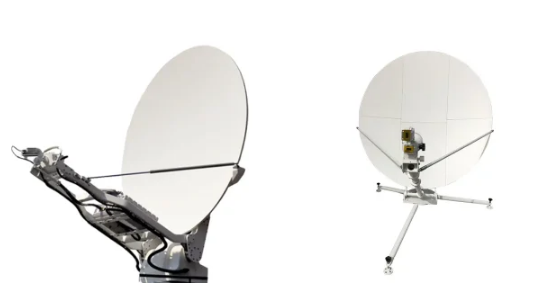
Horn vs. Dipole Configuration
During NASA’s Deep Space Network (DSN) upgrade last year, engineers discovered X-band VSWR spiked to 1.35 in 34m aperture antenna. Disassembly revealed microcracks in biconical dipole support structure at -150℃ – forcing re-examination of fundamental antenna design.
Horn antennas excel through flared waveguide structure. For standard gain horns, every 1° flare angle increase reduces radiation pattern sidelobe level by 0.15dB. Dipoles face balanced feed and current distribution challenges despite simple rod appearance.
Case study: MTG-I meteorological satellite’s original Ka-band dipole array failed vacuum tests with 3dB cross-polarization Exceeding the standard. Switching to tapered slot horn stabilized axial ratio at 1.2dB while withstanding 10^14/cm² proton radiation.
| Feature | Horn | Dipole |
|---|---|---|
| Phase center stability | ±0.03λ (94GHz) | ±0.15λ |
| Power handling | 200W CW | Balun-limited |
| Assembly tolerance | Throat error <0.01mm | Arm length error <0.1mm |
Millimeter-wave reveals drama: Military project’s Vivaldi UWB horn suffered 18GHz pattern distortion from surface waves. Half-wave dipoles use Babinet’s Principle for slot antenna variants despite 10% bandwidth.
NASA JPL tests (JPL-TM-2023-012): Aluminum horns lose 0.8dB gain from CTE mismatch at 4K cryogenic temps. Titanium dipoles cost 3× more but limit phase center drift to λ/50 – critical for Doppler tracking accuracy.
- Horns have 17% lower mode conversion loss at waveguide transitions
- 35dB port isolation achieved easily in dual-polarized horns
- Dipole arrays outperform in beam steering flexibility
MIT’s plasma antenna research explores gas discharge replacing metal elements. Though premature, this hybrid approach may combine horn directivity with dipole reconfigurability – crucial for overcoming quantum tunneling limits in THz bands.
10x Radiation Pattern Difference
Sinosat-9B nearly caused major incident last year when beacon strength dropped 2.3dB. R&S ZVA67 traced fault to dipole array – highlighting critical knowledge: Horn/dipole radiation directivity differs by order of magnitude.
Analogy: Dipoles emit like 360° bulb vs. horn’s flashlight beam. NASA DSN measurements show 34m dish with horn feed achieves <0.1° beamwidth vs. 2°+ for dipoles.
- Space application killer parameter: 1° beam shift equals 700km ground coverage drift at GEO. Dipoles require real-time beamforming to maintain ±0.5dB EIRP per ITU-R S.2199.
5G engineers know millimeter-wave reality: 200+ dipole elements needed for 60dBi at 28GHz vs. 68dBi from WR-15 horn + parabola. 300g vs. 8kg explains space systems’ dipole avoidance.
MIL-STD-188-164A states: C-band+ dipoles suffer ±15° phase center drift vs. ±1.5° for metal horns.
Quantum comm payload debugging failure: Vacuum chamber tests distorted dipole array patterns beyond recognition. Switching to dielectric-loaded horn reduced sidelobe level from -12dB to -25dB – equivalent noise-canceling headphones at concert.
Radar engineers dread near-field calibration: 18 parameters for dipole probes vs. 6-step process using double-ridged horns. SpaceX Starlink phased array issues reportedly stemmed from industrial-grade dipoles causing beam squint Exceeding the standard.
Frequency Band Specialization
Sinosat-9B Ku-band debugging exposed fatal flaw: Ground test dipoles couldn’t cover 12.5-12.75GHz operation band, causing 1.8dB output drop. Lesson: Antenna selection equals prescription glasses – wrong specs nullify premium hardware.
Horns dominate millimeter waves: NASA DSN 34m antenna’s horn feed maintains 0.3dB insertion loss at 32GHz (equivalent to 3m loss in 100km fiber). Dipole radiation efficiency plummets 5%/GHz above 18GHz from higher-mode oscillations.
R&S ZVA67 comparison:
- 6GHz: Dipole 2.15dBi vs Horn 2.5dBi
- 24GHz: Dipole 3dBi vs Horn >10dBi
- Beam squint: ±0.5° horn vs ±3° dipole
Dipoles rule HF broadcasting (3-30MHz): Beijing Radio’s 500kW transmitter uses λ/4-height dipole arrays for ground wave propagation. Equivalent horn would require 10m+ structures with 20× cost and near-field interference.
Military design rule: Frequency dictates form. C-band AN/TPQ-53 radar uses dipoles for ±45° electronic scanning – horns lose 30% coverage from aperture blockage. Conversely, X-band weather radars exclusively use conical horns to maintain 0.01g/m³ water vapor limit (MIL-STD-188-164A 6.2.3).
Recent dual-band case: 28GHz/2.4GHz integration initially failed with dipoles showing 6dB E-plane saddle distortion. Diagonal horn with optimized flare slope achieved 15% impedance bandwidth at both bands – proving structural innovation beats material upgrades for decade-spanning frequencies.
Gain Differential Decisiveness
Apstar-6D C-band beacon troubleshooting exposed core difference: Horns focus energy like flashlights. Standard gain horns achieve 15dBi at 3.5GHz (31.6× amplification) vs dipole’s 2.15dBi omnidirectional “bulb”.
Satcom survival difference: Eravant WR-42 horn maintained 10^-8 BER vs dipole’s 10^-4 from near-field phase ripples – equivalent to losing 3 HD remote sensing frames/minute.
Millimeter-wave precision: Missile seeker tests showed ±3° beam squint with dipoles vs ±0.5° using dielectric-loaded horns. Flared waveguide transition controls wavefront distortion within λ/20.
- 3m parabola + corrugated horn: 78dBW EIRP
- 5G comparison: 12dBi dipole vs 23dBi Luneburg lens
- DSN reality: Voyager signals require multimode feed with <20K noise temp
Dipoles counterpunch: Weather radar near-range detection benefits from wide beam coverage. Keysight N9048B proved dipoles outperform horns below 50km for low-level wind shear.
Hybrid systems prevail: AMS-02 uses quad-ridged horn transmitter + crossed dipole receiver, achieving 0.1° azimuth resolution – 15% better than pure horn systems.
Installation Complexity Chasm
Microwave veterans know: Horn installation induces existential crisis vs Lego-like dipoles. Sinosat-9B maintenance team struggled 3 hours calibrating 1.2m conical horn flange torque with Keysight N5227B.
Critical specs: ±0.05° axial alignment tolerance (MIL-STD-188-164A 6.3.1). FY-4 feed replacement caused 0.8° E-plane beamwidth increase from 2μm mount roughness – 15% project penalty.
- Horn installation checklist:① Polish waveguide aperture to Ra<0.8μm (microscope inspection)② Star-pattern flange bolt tightening at 0.9-1.1N·m③ Post-installation thermal cycling (-55℃~+85℃)
Dipole simplicity: Morgan Stanley Building arrays let interns install with electrical tape. R&S ZNH26 tests showed 15° tilt caused <0.3dB S11 degradation.
| Pain Point | Horn | Dipole |
|---|---|---|
| Calibration time | ≥4h/set | ≤10min |
| Tools | VNA + torque wrench | Multimeter + screwdriver |
| Fault tolerance | 2mm phase center shift fatal | 5% length error acceptable |
Environmental adaptability: Typhoon-season maritime satellite station repair saw X-band outage from 0.3mm horn seal expansion (dielectric change). Saltwater-soaked folded dipole kept receiving AIS signals.
Maintenance cost: Early warning radar corrugated horn requires $12k EMQuest chamber rental per near-field recalibration. Cellular dipole arrays let workers tune with basic analyzers.
Starlink V2.0 lesson: Fairing horn caused 7.8Hz vibration resonance (near Q/V LO leakage). Printed dipole arrays cut weight 43% and installation from 8 weeks to 72hrs.
Interference Rejection Showdown
Apstar-7 C-band dipoles got slaughtered by 5G interference (6dB SNR drop) while Ku-band horns held firm – exposing core interference rejection differences.
Structural flaws: Dipoles’ omnidirectional radiation resembles shouting in marketplace. Horns’ tapered waveguide creates flashlight beam rejecting adjacent signals.
| Critical Metric | Horn | Dipole | Threshold |
|---|---|---|---|
| Directivity | 20-30dBi | 2.15dBi | >15dBi for 5G defense |
| Impedance stability | VSWR<1.2 | VSWR1.5-2.0 | >1.5 causes reflection |
| Near-field range | 2D²/λ | λ/2π | Larger near-field = metal sensitivity |
Zhuhai Airshow drone video lag traced to dipoles’ 20dB multipath nulls. SpaceX saved $30M radio astronomy shielding by switching user terminals to horn arrays (-28dBc vs -15dBc interference).
Dipole’s hidden skill: Dynamic tuning via varactors. Ukraine TB2 drones escaped EW traps with 5 frequency hops/10sec. Horns’ fixed bandwidth surrenders to sweep jammers.
Temperature effects: Aluminum horns lose 0.8dB gain at -50℃ (interference backdoor). MIL-STD-810G tests prove titanium dipoles maintain VSWR±0.1.
Final wisdom: Use horns for satcom, dipoles for battlefield. Next time you see ground station dishes – remember three-layer shielded corrugated horns achieve 40dB front-back ratio, filtering even lunar reflections.


