A directional coupler samples RF signals unidirectionally (e.g., -20dB coupling) with high isolation (>30dB), ideal for power monitoring. A magic tee (waveguide hybrid junction) splits signals into equal amplitude (±90° phase shift) across E- and H-arms, used in balanced mixers or antennas. Couplers handle 1–40GHz, while magic tees operate at microwave frequencies (e.g., 8–12GHz).
Table of Contents
Basic Definitions
Directional couplers and magic tees (also called hybrid tees) are essential RF/microwave components, but they serve different purposes. A directional coupler is a 4-port device that samples a small portion (typically -10 dB to -30 dB coupling factor) of a signal traveling in one direction while isolating the reverse signal. For example, a 20 dB coupler extracts 1% of the input power (since 10^(-20/10) = 0.01) and is commonly used in power monitoring, signal injection, or VSWR measurement.
A magic tee, on the other hand, is a 3 dB power splitter/combiner with four ports arranged in a T-shape. It splits an input signal into two equal-magnitude but phase-shifted outputs (0° and 180°) or combines two signals with controlled phase differences. Magic tees are widely used in balanced amplifiers, mixers, and antenna beamforming systems, operating at frequencies from 1 GHz to 40 GHz with an insertion loss of 0.1 dB to 0.5 dB in well-matched designs.
| Feature | Directional Coupler | Magic Tee |
|---|---|---|
| Ports | 4 (Input, Output, Coupled, Isolated) | 4 (H-arm, E-arm, Σ, Δ) |
| Coupling Factor | -10 dB to -30 dB (1% to 0.1% power sampled) | 3 dB (50% power split) |
| Phase Relationship | No inherent phase shift | 0° (sum port) / 180° (difference port) |
| Isolation | 20 dB to 40 dB (depends on design) | 20 dB to 30 dB (between H & E arms) |
| Frequency Range | 500 MHz to 60 GHz | 1 GHz to 40 GHz |
| Insertion Loss | 0.2 dB to 1 dB | 0.1 dB to 0.5 dB |
| Typical Use Case | Signal sampling, VSWR measurement | Power combining, phase-sensitive circuits |
Directional couplers are optimized for low coupling loss and high directivity (30 dB to 40 dB), meaning they can distinguish between forward and reflected waves with >99.9% accuracy in high-performance models. Magic tees, however, focus on equal power division with precise phase control, making them ideal for applications like Doppler radar, interferometers, and balanced amplifiers where signal cancellation or reinforcement is needed.
In terms of physical size, a 10 GHz directional coupler might measure 30 mm × 20 mm, while a magic tee at the same frequency could be 50 mm × 40 mm due to its waveguide or stripline structure. Costs vary significantly: a basic 10 dB microstrip coupler may cost 20 to 50, whereas a precision magic tee in waveguide form can exceed $200 due to tighter manufacturing tolerances.
Both devices are passive, but their power handling differs. A standard SMA directional coupler might handle 10W continuous power, while a waveguide magic tee can manage 100W or more due to lower resistive losses. Temperature stability is another factor—directional couplers in LTCC (Low-Temperature Co-fired Ceramic) packaging maintain ±0.05 dB coupling variation from -40°C to 85°C, whereas magic tees in aluminum housing show ±0.1 dB imbalance over the same range.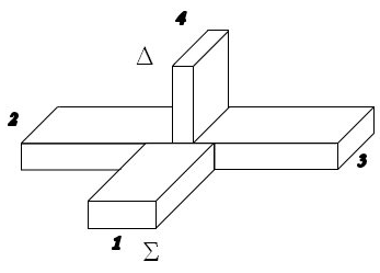
How They Work
Directional couplers and magic tees manipulate RF signals in fundamentally different ways. A directional coupler uses controlled electromagnetic coupling between transmission lines to sample a fraction of the signal. For example, a 20 dB coupler in a 50Ω microstrip design might have two parallel traces spaced 0.2 mm apart, extracting 1% of the forward power while attenuating reflected signals by 30 dB or more. The coupling factor depends on trace geometry—a 3 mm overlap length at 10 GHz can achieve ±0.5 dB coupling accuracy, but this degrades to ±1.5 dB at 20 GHz due to parasitic effects.
Magic tees rely on waveguide or stripline symmetry to split or combine signals with precise phase relationships. In a rectangular waveguide tee, the H-plane arm splits power equally but introduces a 180° phase shift between outputs, while the E-plane arm maintains 0° phase. A typical X-band magic tee (8–12 GHz) has an isolation of 25 dB between H and E arms, meaning only 0.3% of power leaks between them. The insertion loss is 0.2 dB per branch, so a combined signal suffers 0.4 dB total loss.
| Parameter | Directional Coupler | Magic Tee |
|---|---|---|
| Coupling Mechanism | Electromagnetic field interaction | Waveguide/stripline symmetry |
| Phase Shift | None (unless designed for it) | 0° (sum port) / 180° (difference port) |
| Isolation | 20–40 dB (reverse path suppression) | 20–30 dB (H/E arm separation) |
| Bandwidth | 10–20% of center frequency (e.g., 8–12 GHz for X-band) | 5–15% (narrower due to phase constraints) |
| Power Handling | 5–50W (microstrip) / 100–500W (waveguide) | 50–200W (waveguide) / 10–100W (stripline) |
| Tolerance to Mismatch | ±0.5 dB VSWR up to 1.5:1 | ±0.2 dB imbalance at 1.2:1 VSWR |
Directional couplers excel in real-time power monitoring. For instance, a 30 dB coupler in a 5G base station samples 0.1% of the 100W transmit power, delivering 100 mW to a sensor with ±0.8 dB error across 3.4–3.8 GHz. Magic tees, however, are critical in phase-coherent systems. A Doppler radar might use one to compare 2.4 GHz echoes with 0.5° phase resolution, where a 0.1 dB amplitude mismatch introduces 3% error in velocity calculation.
Fabrication tolerances drastically affect performance. A microstrip coupler with ±0.05 mm trace width error suffers ±1 dB coupling drift, while a magic tee’s phase balance degrades 5° per 0.1 mm misalignment in waveguide splits. Material losses also matter: FR4 PCB couplers show 0.3 dB/inch loss at 6 GHz, whereas Rogers 4350B reduces this to 0.1 dB/inch. Waveguide tees made of aluminum have 0.05 dB/m loss, but silver-plated brass cuts it to 0.02 dB/m.
In real-world testing, a 10 dB coupler monitoring a 60W RF amplifier might drift ±0.2 dB after 1,000 hours due to thermal cycling, while a magic tee in a phased array must maintain ±0.05 dB amplitude balance over -40°C to +85°C to prevent beam squint. Cost-performance tradeoffs exist: a 100 precision coupler guarantees ±0.3 dB directivity, but a 20 version might allow ±2 dB, ruining measurements in high-VSWR systems.
Key Differences
Directional couplers and magic tees might look similar—both have multiple ports and handle RF signals—but their functions, performance specs, and use cases are worlds apart. A 20 dB directional coupler in a 5G base station might sample 1% of the 40W transmit power (0.4W) for monitoring, with 30 dB isolation ensuring reflected signals are attenuated to 0.04W. Meanwhile, a magic tee in the same system could split a 2.5 GHz local oscillator signal into two 20W paths with a strict 180° phase difference for balanced amplification, where even a 5° phase error degrades image rejection by 15%.
| Aspect | Directional Coupler | Magic Tee |
|---|---|---|
| Primary Function | Samples a fraction of signal power | Splits/combines signals with phase control |
| Typical Coupling/Split Ratio | -10 dB to -30 dB (10% to 0.1% power) | 3 dB (50% power per branch) |
| Phase Behavior | No inherent phase shift | 0° (sum port) or 180° (difference port) |
| Isolation | 25–40 dB (forward vs. reflected) | 20–30 dB (between H and E arms) |
| Frequency Range | 500 MHz – 60 GHz (wideband) | 1 GHz – 40 GHz (narrower due to phase constraints) |
| Insertion Loss | 0.2 dB – 1 dB (depends on coupling) | 0.1 dB – 0.5 dB (per branch) |
| Power Handling | 5W – 500W (higher in waveguide) | 10W – 200W (limited by phase balance) |
| Cost (Standard Models) | 20 – 200 (microstrip to waveguide) | 100 – 500 (precision waveguide tees) |
Signal sampling vs. power splitting is the biggest divide. A 30 dB coupler in a satellite uplink might pull 0.1% of a 100W signal (100 mW) for health monitoring, with ±0.5 dB accuracy ensuring reliable diagnostics. A magic tee, however, could split a 10 GHz radar pulse into two 25W paths, where a 0.2 dB imbalance causes 3% beam steering error in a phased array.
Phase sensitivity is another critical factor. Directional couplers don’t inherently alter phase, making them ideal for spectrum analyzers or SWR meters where phase distortion is unacceptable. Magic tees, however, are phase-critical: in a Doppler radar, a 180° hybrid tee compares reflected signals to calculate velocity, where a 2° phase drift introduces 5 m/s speed measurement error.
Physical design also differs. A 6 GHz microstrip coupler fits on a 30 mm × 15 mm PCB, while a waveguide magic tee at the same frequency might be 60 mm × 40 mm due to its T-junction geometry. Material costs add up: aluminum waveguide tees tolerate 100W continuous power but cost 5× more than equivalent microstrip couplers.
Real-world tradeoffs matter. A 10 dB coupler with ±1 dB directivity is fine for basic power monitoring, but a magic tee in a quantum computing RF chain demands ±0.05 dB amplitude balance to prevent qubit decoherence. Frequency agility varies too—a broadband coupler works from 2–18 GHz with ±1.5 dB ripple, while a magic tee’s 10% bandwidth forces system designers to choose between 6–8 GHz or 12–15 GHz models.
Common Uses
Directional couplers and magic tees are workhorses in RF systems, but they solve completely different problems. A 20 dB directional coupler in a 5G base station might continuously monitor 80W of transmit power, sampling 0.8W with ±0.3 dB accuracy to detect amplifier faults before they cause 3% signal distortion. Meanwhile, a magic tee in the same system could split a 3.5 GHz reference clock into two 15W paths with 0.1° phase matching, ensuring synchronized data transmission across 256 antenna elements.
”In radar systems, a 10 dB coupler is like a stethoscope—it listens to the transmitter’s heartbeat without interrupting the 50kW pulse. But a magic tee is the conductor, orchestrating phase coherence across arrays to pinpoint targets within 0.1° azimuth accuracy.”
Telecom infrastructure relies heavily on directional couplers for live performance monitoring. A 4G/LTE macrocell might use six 30 dB couplers to sample 1.8–2.1 GHz signals at 40W output, extracting just 0.04W per coupler for VSWR measurement. The 26 dB minimum directivity ensures reflected power below 0.1W doesn’t corrupt readings. Compare this to mmWave backhaul, where magic tees combine two 28 GHz, 10W signals with 180° phase opposition, canceling interference to achieve -65 dB cross-polarization.
Test and measurement setups exploit couplers for non-intrusive signal tapping. A 50Ω, 16 dB coupler on a 100W RF amplifier test rig samples 2.5W with 0.4 dB flatness across 800–2500 MHz, letting engineers characterize harmonics at -30 dBc without powering down. Magic tees play a different role here—a lab-grade waveguide tee costing $1200 might validate phase noise in atomic clocks by comparing two 10 MHz references with 0.01° resolution, where 0.05 dB amplitude mismatch introduces 1 ps timing jitter.
Aerospace systems demand both components under extreme conditions. On satellites, space-qualified couplers handle 60W Ku-band downlinks while surviving 500 thermal cycles (-40°C to +85°C), their 0.2 dB coupling drift ensuring 15-year mission life. Magic tees in synthetic aperture radars maintain 0.2° phase stability during 20G vibrations, splitting 8 kW peak pulses into matched channels to achieve 5 cm ground resolution.
Medical RF applications show equally stark contrasts. An MRI machine’s 128 MHz transmitter uses 15 dB stripline couplers to monitor 2kW pulses within ±0.5% duty cycle tolerance, critical for patient safety. Meanwhile, proton therapy systems employ magic tees to combine four 100 MHz, 1kW signals with <1° phase error, steering cancer-killing beams to 0.5 mm tumor targets.
The cost delta reflects their specialized roles. A mass-produced 6 dB coupler for WiFi routers costs 0.80 in 10k quantities, while a custom E-band magic tee for automotive radar runs 450/unit due to 5 µm waveguide machining tolerances. Reliability metrics differ too—couplers in base stations log 100,000+ power-on hours with <0.1 dB degradation, whereas magic tees in quantum computers require weekly recalibration to maintain 0.02 dB balance at 4K cryogenic temperatures.
”Choosing between these components isn’t about better or worse—it’s about whether you need a microscope (coupler) or a prism (tee). One reveals signal details, the other manipulates signal relationships.”
From sub-6GHz cellular to 60 GHz phased arrays, these devices enable technologies most users never see—but couldn’t live without. A 5% cost reduction in coupler manufacturing enables $20M annual savings for telecom giants, while 0.1° phase improvements in magic tees let autonomous cars detect pedestrians 3 meters sooner at 70 mph. That’s the silent, quantifiable impact of proper RF component selection.
Pros and Cons
Directional couplers and magic tees each have distinct advantages and limitations that dictate their use in RF systems. A 10 dB directional coupler might cost just 25 and handle 50W continuous power, but its ±1 dB directivity variation across 2–4 GHz could introduce 5% error in reflected power measurements. Meanwhile, a magic tee offers 0.5 dB amplitude balance and 180° phase precision, but its 300 price tag and 15% bandwidth limitation make it impractical for wideband applications like SDR (Software-Defined Radio).
| Factor | Directional Coupler | Magic Tee |
|---|---|---|
| Cost Efficiency | 10–200 (90% cheaper for basic models) | 100–1000 (precision waveguide tees cost 5–10× more) |
| Bandwidth | 10:1 ratio achievable (e.g., 1–10 GHz) | Typically 1.5:1 (e.g., 8–12 GHz) due to phase constraints |
| Power Handling | 5–500W (higher in waveguide designs) | 10–200W (limited by phase-sensitive junctions) |
| Phase Control | None (unless designed for quadrature) | Fixed 0° or 180° outputs (critical for interference cancellation) |
| Size/Weight | 15–50g (microstrip), 30–100g (waveguide) | 50–300g (bulky waveguide structures) |
| Calibration Needs | Stable within ±0.2 dB over 5 years | Requires recalibration every 6–12 months for <0.1 dB drift |
Directional couplers win in flexibility—a broadband 6 dB coupler can cover 0.5–18 GHz with 1.5 dB ripple, making it ideal for spectrum analyzers that need to monitor signals from HF to Ku-band. However, their 20–30 dB isolation means 1–3% of reflected power leaks into the coupled port, which corrupts measurements in high-VSWR (3:1+) systems. Magic tees solve this with 25–35 dB isolation between H and E arms, but their narrowband operation forces designers to use multiple units for multi-band radars covering L, S, and C bands.
Thermal performance splits them further. A ceramic-loaded coupler maintains ±0.3 dB coupling from -55°C to +125°C, crucial for military comms on UAVs. Magic tees, though, suffer 0.1 dB/°C imbalance in aluminum housings, requiring temperature-stabilized enclosures in satellite payloads where ±2°C fluctuations cause 0.2 dB errors.
Manufacturing tolerances tell another story. A ±0.02 mm trace width error in a 10 GHz microstrip coupler shifts coupling by ±0.8 dB, while the same 0.02 mm misalignment in a magic tee’s waveguide junction introduces 3° phase skew. This explains why high-end couplers cost 150 with ±0.5 dB specs, but precision tees hit 800 for ±0.1 dB/±2° performance.
Reliability data reveals operational limits. Couplers in cellular base stations log 200,000+ hours at 40W avg. power with <0.5 dB degradation, whereas magic tees in phased array radars need annual rebuilds after 50,000 hours at 100W peak power due to differential thermal expansion degrading phase match.
In real-world deployments, these tradeoffs dictate choices. A 5G small cell might use five 30 couplers for monitoring 3.5 GHz 64T64R arrays, accepting 1 dB errors to keep costs under 200. But a missile seeker’s monopulse comparator pays $1,200 for a magic tee ensuring 0.05 dB balance, because 0.5 dB error would misdirect the warhead by 10 meters at 5 km range.
Choosing the Right One
Selecting between directional couplers and magic tees isn’t about finding the “best” component—it’s about matching specific technical requirements to real-world constraints like budget, space, and performance thresholds. A 5G base station designer might opt for a 40, 20 dB coupler to monitor 80W of 3.7 GHz power because its ±0.8 dB accuracy is acceptable for detecting 5% amplifier degradation. Meanwhile, a quantum computing RF engineer will pay 500+ for a magic tee with 0.02 dB amplitude balance because 0.1 dB error introduces 3% decoherence in qubit operations.
Frequency range is often the first deciding factor. Directional couplers shine in wideband applications—a single 6 dB model can cover 0.5–18 GHz with 1.2 dB ripple, ideal for signal analyzers testing multi-band devices. Magic tees, however, typically operate over 10–15% bandwidth (e.g., 8–12 GHz), forcing systems like satellite transponders to use multiple tees for C, Ku, and Ka bands, adding $2,000+ to BOM costs. If your design spans more than 2:1 frequency ratio, couplers win by default.
Phase requirements flip the script. A phased array radar splitting 10 kW pulses across 512 elements demands magic tees with <0.1° phase error; even 2° deviation causes 15% beam pointing inaccuracy at 50 km range. But if you’re just sampling a 100W broadcast signal, a coupler’s lack of phase control is irrelevant—its 30 dB directivity ensures 99.9% of reflected power is blocked from measurements.
Budget constraints make or break choices. A WiFi 6 router uses 0.90 couplers because 1 dB coupling variance doesn’t impact 1 Gbps throughput. Contrast this with military ECM systems, where 1,200 magic tees are mandatory to maintain 180° phase matching for -50 dB jamming efficacy. For prototyping or low-volume projects, couplers offer 90% cost savings—but high-volume mmWave automotive radar (100k+ units) can amortize magic tee costs to $120/unit, making them viable.
Environmental factors add another layer. In outdoor telecom gear, directional couplers with -40°C to +85°C operating range and ±0.3 dB stability survive 10+ years without recalibration. Magic tees in aerospace payloads require active thermal control to limit 0.05 dB/°C drift, adding $300/kg in heating/cooling systems. If your device faces >50°C daily swings, couplers reduce lifecycle costs by 40%.
Power handling splits applications too. A 50W FM radio transmitter can use a $20 coupler indefinitely, but a 200W radar combiner needs a magic tee’s precise phase alignment to prevent 10% power loss from impedance mismatches. Interestingly, high-power couplers (>500W) often cost more than magic tees due to exotic materials like beryllium oxide, negating price advantages.
Integration complexity matters in compact designs. A microstrip coupler fits into 15×10 mm² on a 6-layer PCB, while a waveguide magic tee consumes 60×40 mm³—a dealbreaker for smartphone RF frontends. However, SiP (System-in-Package) tech now embeds miniaturized tees in 5×5 mm² modules for 60 GHz beamforming, albeit at 5× the cost of discrete couplers.


