A directional coupler splits RF signals asymmetrically (e.g., 90:10 ratio) with 20-30 dB isolation to monitor power without disrupting flow, while a combiner merges signals symmetrically (e.g., 3dB loss) with <0.5dB insertion loss. Couplers operate at 1-40GHz for measurement, combiners at narrow bands for coherent summation—critical differences in phase matching (±2°) and VSWR (<1.5:1).
Table of Contents
Basic Working Principle
A directional coupler and a combiner are both passive RF components, but they work in fundamentally different ways. A directional coupler samples a small portion (typically 1% to 30%) of the signal power traveling in one direction while allowing the rest to pass through with minimal loss (<0.5 dB in high-quality models). For example, a 20 dB coupler extracts 1% of the input power for monitoring or measurement, while 99% continues to the output. These devices operate over a wide frequency range (500 MHz to 40 GHz in some models) and are commonly used in signal monitoring, SWR measurement, and feedback systems.
In contrast, a combiner merges two or more input signals into a single output, with the goal of minimizing insertion loss (<1 dB in well-designed units). A typical 2-way combiner might handle 10W to 1000W of combined power, depending on design. Unlike couplers, combiners are bidirectional—signals can flow from input to output or vice versa. They are essential in RF transmitters, antenna systems, and power-sharing setups where multiple sources feed a single load.
| Feature | Directional Coupler | Combiner |
|---|---|---|
| Primary Function | Samples a portion of a signal | Combines multiple signals |
| Power Handling | Typically 1W to 500W | 10W to 10kW+ (depends on type) |
| Insertion Loss | 0.2 dB to 1 dB | 0.5 dB to 3 dB |
| Isolation | 20 dB to 40 dB (between ports) | 10 dB to 30 dB (between inputs) |
| Frequency Range | 500 MHz – 40 GHz | DC – 18 GHz (varies by design) |
Directional couplers rely on electromagnetic coupling between transmission lines. In microstrip designs, two parallel traces spaced 0.5 mm to 2 mm apart achieve coupling factors from 6 dB to 30 dB. The sampled signal (coupled port) is frequency-sensitive, meaning performance varies across bands. For instance, a 10 dB coupler at 2 GHz might degrade to 12 dB at 4 GHz due to wavelength effects.
Combiners, however, use resistive, hybrid, or Wilkinson designs. A Wilkinson combiner offers low loss (<0.3 dB) and high isolation (>20 dB) but only works within a narrow bandwidth (10-20% of center frequency). Resistive combiners (3 dB loss per combined signal) are broadband but inefficient for high-power applications.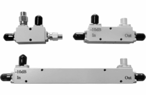
Key Performance Differences
When choosing between a directional coupler and a combiner, the performance specs make or break your application. A directional coupler excels in signal monitoring with minimal disruption, typically leaking -10 dB to -30 dB (10% to 0.1%) of the main signal to a coupled port while keeping insertion loss under 0.5 dB. In contrast, a combiner prioritizes power efficiency, merging signals with 0.3 dB to 3 dB loss depending on design. For example, a Wilkinson combiner at 2 GHz might lose only 0.2 dB per path, while a resistive combiner wastes 3 dB (50% power loss) no matter what.
| Parameter | Directional Coupler | Combiner |
|---|---|---|
| Insertion Loss | 0.2 dB – 1 dB | 0.3 dB – 3 dB |
| Isolation | 20 dB – 40 dB (input to coupled port) | 10 dB – 30 dB (input-to-input) |
| Power Handling | 1W – 500W (avg.), up to 10kW (high-power) | 10W – 10,000W+ (depends on cooling) |
| Frequency Stability | ±0.5 dB variation over 500 MHz – 40 GHz | ±1 dB variation in narrowband (10% BW) designs |
| Temperature Drift | ±0.3 dB from -40°C to +85°C | ±1 dB (resistive), ±0.5 dB (hybrid) |
Directional couplers are precision tools—a 20 dB coupler in a 5G mmWave setup (28 GHz) must maintain ±0.2 dB coupling accuracy to avoid calibration errors. If the coupled port drifts by 1 dB, your signal analysis could be off by 25%. Meanwhile, combiners deal with raw power. A 4-way TV broadcast combiner handling 4 x 5 kW inputs must keep insertion loss below 0.5 dB, or you’re dumping 500W+ as heat.
Frequency response is another key divider. A broadband coupler (2–18 GHz) might see coupling factor swings of ±2 dB, while a narrowband hybrid combiner stays flat within ±0.3 dB at its tuned frequency (e.g., 1.8 GHz ±5%). If you try to use a 900 MHz combiner at 2.4 GHz, isolation could drop from 25 dB to 10 dB, causing crosstalk.
Common Use Cases
Directional couplers and combiners solve completely different problems in RF systems, and choosing the wrong one can cost you performance, efficiency, or even equipment safety. A directional coupler is your go-to when you need to monitor or sample a signal without disturbing it—think of it as a “tap” that steals 0.1% to 10% of the power for analysis while letting 90-99.9% pass through untouched. On the other hand, a combiner is all about merging power—whether you’re feeding multiple transmitters into one antenna or summing signals for higher output, it’s designed to minimize loss (0.2 dB to 3 dB) while keeping inputs from interfering with each other.
Where You’ll Find Them in Real Systems
| Application | Device Used | Key Specs | Why It’s Used |
|---|---|---|---|
| 5G Base Stations | Directional Coupler | 20 dB coupling, 0.3 dB insertion loss, 6 GHz max | Monitors TX power (100W+) without disrupting signal |
| FM Radio Broadcast | Hybrid Combiner | 4-way, 0.5 dB loss, 10 kW per port | Combines multiple 5 kW transmitters into one antenna |
| Satellite Comms | Directional Coupler | 30 dB coupling, 0.2 dB loss, 40 GHz range | Samples millimeter-wave signals for fault detection |
| Wi-Fi Routers (MIMO) | Power Divider (Combiner) | 2-way, 3.5 dB loss, 2.4/5 GHz | Splits/combines signals for multiple antennas |
| RFID Readers | Directional Coupler | 10 dB coupling, 1 dB loss, 900 MHz | Detects reflected signals for tag presence/range |
Directional couplers shine in precision applications:
- In cellular networks, a 20 dB coupler samples 1% of a 50W signal to check for distortion or interference, ensuring the main 49.5W keeps flowing to the antenna.
- Radar systems use high-directivity (40 dB) couplers to monitor pulse shapes (1-10 ns width) without loading the transmitter. A 0.5 dB loss here is acceptable, but poor isolation (>20 dB) could distort measurements.
- Lab equipment (like spectrum analyzers) relies on 6 dB to 30 dB couplers to safely tap into high-power (100W+) signals without frying sensitive inputs.
Combiners handle heavy lifting in power-critical setups:
- FM radio stations merge four 10 kW transmitters into a single 38 kW feed (after 0.5 dB loss per path). A resistive combiner would waste 50% power, but a hybrid combiner keeps efficiency above 90%.
- Military jammers use wideband (2-18 GHz) combiners to blend multiple noise sources into one high-power output. If isolation drops below 15 dB, the jamming signals interfere with each other.
- Cell tower amplifiers often combine two 100W PAs for 190W total output (after 0.3 dB loss)—cheaper than buying a single 200W amp.
Cost vs. Performance Trade-offs
- A basic 10 dB coupler costs 20-100, but a 40 GHz aerospace-grade version runs $500+.
- A resistive 2-way combiner is 10 (but loses 3 dB = 50% power), while a 0.2 dB loss Wilkinson combiner costs 200+.
Mistakes to Avoid
- Using a combiner as a coupler (you’ll lose half your signal).
- Pushing a 10W coupler with a 100W input (it’ll fry in seconds).
- Ignoring frequency range—a 900 MHz combiner at 2.4 GHz may have >10 dB worse isolation.
Signal Flow Comparison
Understanding how signals move through directional couplers versus combiners is crucial for proper system design. While both devices handle RF energy, their signal paths behave in fundamentally different ways. A directional coupler operates asymmetrically—90-99.9% of input power (1-100W) flows straight through to the output port, while 0.1-10% gets diverted to a coupled port for monitoring. In contrast, a combiner works bidirectionally, merging two or more input signals (10W-10kW each) into a single output with 0.3-3dB loss, or equally splitting one signal to multiple outputs.
Key difference:
Directional couplers maintain >20dB isolation between forward/reflected paths, while combiners deliberately mix signals with 10-30dB isolation between input ports. This makes couplers ideal for non-intrusive measurements, whereas combiners excel at power summation.
Directional coupler signal behavior follows strict path dependency. When 50W at 2.4GHz enters the input port:
- 49.5W (99%) exits the output port with <0.5dB loss
- 0.5W (1%) appears at the coupled port (20dB coupling)
- The isolated port typically shows >30dB suppression, meaning <0.05W leakage
- Reverse flow (output to input) maintains >20dB directivity, preventing measurement errors
Combiner signal flow varies dramatically by type:
- Wilkinson combiners provide 0.2-0.5dB loss per path but only work within ±10% bandwidth of center frequency (e.g., 1.8-2.0GHz for a 1.9GHz model)
- Resistive combiners exhibit flat 3dB loss across DC-6GHz, making them broadband but inefficient
- Hybrid combiners maintain 90° phase shift between outputs with ±5° tolerance, critical for phased arrays
Phase coherence presents another critical distinction. A high-quality directional coupler introduces <5° phase shift across its operating band, while combiners may impose 15-30° phase differences between ports. This becomes critical when:
- Aligning signals for beamforming arrays (requires <10° error)
- Maintaining pulse timing in radar systems (where 1ns = 36° at 100MHz)
- Preserving QAM constellation accuracy in 5G (tolerates only 2-3° distortion)
Real-world signal flow impacts:
- In a 5G massive MIMO setup, using a combiner instead of a coupler for signal monitoring would waste 50% power (3dB loss) and potentially distort phase relationships
- Attempting to use a directional coupler for power combining limits you to <10% efficiency, as 90% of energy remains in the main path
- Temperature variations cause 0.1-0.5° phase drift per °C in couplers versus 0.5-2° per °C in combiners—critical for outdoor deployments experiencing -40°C to +85°C swings
Practical rule:
Need to sample or measure without disruption? Use a coupler. Need to merge or split power efficiently? Use a combiner. Mixing them up costs 3-10dB in performance loss and risks system instability.
Frequency-dependent behavior further separates these devices. A 6-18GHz coupler might maintain ±0.5dB coupling flatness, while a combiner’s isolation could vary by ±3dB across the same band. This becomes critical when:
- Operating wideband systems (e.g., electronic warfare gear covering 2-40GHz)
- Maintaining consistent SNR across channels (where 1dB change = 25% power difference)
- Meeting military specs like MIL-STD-461 requiring <0.5dB ripple in test setups
Insertion loss patterns tell the final story. While both devices cause some loss:
- Coupler losses stay constant relative to frequency (e.g., 0.4dB ±0.1dB from 1-6GHz)
- Combiner losses often show peak-to-valley swings of 1-2dB across their bandwidth
- High-power combiners (>1kW) exhibit 0.1-0.3dB higher losses at 85°C versus 25°C due to conductor heating
Power Handling Capacity
Power handling is where directional couplers and combiners show their hard limits—push them too far, and they overheat, detune, or fail catastrophically. A typical directional coupler for lab use might handle just 1-10W, while industrial-grade models survive 500W continuous or 5kW pulsed. Combiners, built for power merging, often start at 50W and scale to 100kW+ in broadcast systems. The difference comes down to heat dissipation, material quality, and design efficiency—a 20 coupler burns out at 20W, while a 2,000 combiner runs 10kW for decades.
Power Limits by Device Type
| Parameter | Directional Coupler | Combiner |
|---|---|---|
| Typical Continuous Power | 1W – 500W | 50W – 100kW |
| Peak Pulse Power | 100W – 5kW (1% duty cycle) | 200W – 200kW (short bursts) |
| Thermal Failure Point | 80°C – 120°C (ferrite cores degrade) | 150°C – 200°C (ceramic substrates tolerate more) |
| Power Density | 5 – 50 W/cm³ (limited by trace width) | 100 – 500 W/cm³ (bulkier conductors) |
| Derating Curve | -0.5% power/°C above 25°C | -0.3% power/°C above 25°C |
Directional couplers face two hard limits:
- Main line current: A microstrip coupler with 0.5mm traces overheats at 3A (≈20W at 50Ω), while a thick-film design handles 10A (200W).
- Coupled port sensitivity: Even if the main line survives 100W, the coupled port’s thin-film resistors may fry at 1W sampled power (for a 20dB coupler).
Combiners prioritize raw power tolerance:
- A Wilkinson combiner using λ/4 transformers spreads heat across 2–5cm², handling 500W continuous with 0.2dB loss.
- A resistive combiner dumps 50% power as heat—a 100W input means 50W must dissipate, requiring heat sinks or forced air cooling.
- Waveguide combiners in radar systems manage 10kW+ by distributing fields across 20–50cm³ volumes.
Real-World Power Failures
- A 5G base station using a 10W-rated coupler for 100W signals fails within hours—the FR4 substrate delaminates at 110°C.
- An AM radio station pushing 50kW through a 30kW-rated combiner sees 0.5dB loss spike to 3dB as internal arcing begins.
- Military jammers running 1kW pulses at 10% duty cycle require combiners with 10× peak/avg. power ratings to avoid thermal shock.
Material Matters
- Cheap couplers use FR4 (1W/cm² tolerance), while aerospace models use Rogers 4350B (10W/cm²).
- Combiners for 6GHz+ often switch to alumina ceramics (20W/cm²) or air-dielectric designs to avoid dielectric losses.
Derating by Environment
- At 70°C ambient, a 100W coupler derates to 65W, while a 1kW combiner drops to 800W.
- Humidity >80% cuts power ratings 20–30% due to surface leakage risks.
Cost vs. Power Trade-offs
- A 500W coupler costs 500–2,000, while a 500W combiner runs 100–500.
- High-power (10kW+) combiners demand water cooling ($5,000+ systems), adding 30% to operational costs.
Key Design Rules
- Always operate couplers ≥10dB below their rated power for longevity.
- For combiners, keep peak-to-average power ratios <10:1 to avoid arcing.
- Monitor case temperature—>85°C on couplers or >120°C on combiners signals imminent failure.
Choosing the Right Device
Picking between a directional coupler and a combiner isn’t about “which is better”—it’s about which solves your specific problem without wasting power, money, or space. A 200 high-directivity coupler is useless if you need to merge two 50W signals, just like a 50 combiner will wreck your measurements if you try to sample a 5G mmWave signal. The right choice depends on frequency, power, isolation needs, and budget, with trade-offs that can cost 3dB (50% power loss) or ±1dB measurement errors if ignored.
| Scenario | Use a Coupler When… | Use a Combiner When… |
|---|---|---|
| Signal Monitoring | You need to sample 0.1–10% of a signal with <0.5dB disturbance | Never—combiners destroy signal integrity for monitoring |
| Power Merging | Never—couplers waste 90%+ power in combining tasks | You’re merging ≥2 signals and can tolerate 0.3–3dB loss |
| Frequency Range | Operating >6GHz (couplers handle 40GHz+ better than most combiners) | Operating <6GHz (combiners dominate DC–6GHz for power apps) |
| Isolation Needs | You need >20dB isolation between forward/reflected paths | You need 10–30dB isolation between input ports |
| Budget Constraints | You can spend 50–500 for precision | You need 20–200 for power handling |
Frequency first, power second. A 2.4GHz Wi-Fi amplifier needing signal feedback requires a 10dB coupler with 1W handling (60), while a FM radio station merging 4×5kW signals needs a hybrid combiner (3,000). But if you try to use that coupler at 28GHz, its performance may degrade from ±0.5dB flatness to ±2dB ripple, ruining 5G beamforming calibration.
Power tolerance is non-negotiable. A 100W coupler running at 150W fails 10× faster due to dielectric heating, while a 10kW combiner at 15kW risks internal arcing. Always derate specs by 20% for safety—if you need 100W handling, buy a 125W+ rated device.
Isolation requirements dictate design.
- For VSWR monitoring, a coupler needs >25dB directivity to separate forward/reflected waves accurately.
- For transmitter combining, a combiner needs >20dB isolation to prevent oscillator pulling between PAs.
- Cheap resistive splitters offer only 6dB isolation, causing crosstalk in MIMO systems.
Physical constraints matter:
- A 40GHz coupler fits in 10×10mm, but a 50kW combiner needs 300×300mm + heat sinks.
- PCB trace width limits power—0.2mm traces handle 5W, while 2mm traces manage 50W.
Cost vs. performance breakpoints:
- Couplers: Pay 100–300 for ±0.2dB accuracy, or 20–50 for ±1dB (fine for non-critical apps).
- Combiners: 50 gets you 3dB loss (resistive), 200 buys 0.5dB loss (Wilkinson), and $1,000+ delivers 0.2dB (aerospace hybrid).
Real-World Mistakes to Avoid:
- Using a 900MHz combiner for 2.4GHz Wi-Fi—isolation drops from 25dB to 10dB, causing packet errors.
- Sampling 100W radar pulses with a 10W coupler—the coupled port fries at 1W sampled power.
- Ignoring temperature derating—a 50W coupler at 85°C handles only 35W.
Pro Tip:
- For test benches, prioritize couplers with ±0.1dB flatness and >30dB directivity.
- For field deployments, choose combiners with 0.5dB loss max and IP67 enclosures if outdoors.