Waveguides confine high-frequency waves, minimizing loss over distance, while transmission lines are versatile, used for a broader frequency range.
Table of Contents
Types and Structures
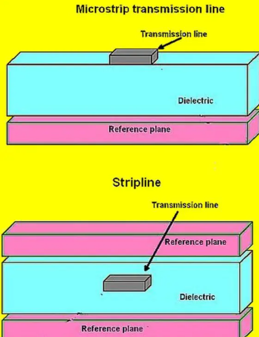
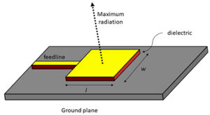
Types of Transmission Lines Transmission lines are used to transmit electrical signals from one point to the other. Common types include coaxial cables, twisted pairs, and microstrip lines. Coaxial cables have a central conductor, insulator, and a metallic shield, exhibiting high bandwidths and noise immunity; thus, they are used in radio frequency applications. Twisted pair cables are also typical, especially in the telecommunications sector since they contain pairs of wires twisted together, promoting electromagnetic compatibility . Microstrip lines are also common in microwave circuits and most of the high-frequency circuits as they have conducting strips on the insulating board, ensuring that the production cost is maintained, and there is a balance in the performance.
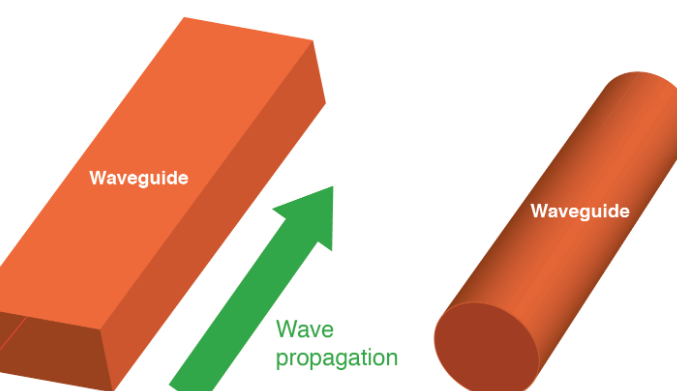
Types of Waveguides Waveguides refer to devices used to guide electromagnetic waves from one point to another, and they are typically used at microwave frequencies. Rectangular and circular waveguides are also common and are utilized at different frequency bands to minimize the loss. Rectangular waveguides are able to satisfy TE and TM modes and are used in a wide range of applications from radar to satellite communication. Circular waveguides are also common and offer the ability to support a wide range of modes, an added advantage since they can be used in any application, especially those requiring rotation, such as the rotary joints. Optical fibers are also common, and they are dielectric waveguides that offer low losses, used in applications for transmitting light.
Comparative Structures of Transmission Lines and Waveguides Transmission lines and waveguides are types of apparatus used in numerous applications, but they differ as illustrated above. The transmission lines have coaxial cables, twisted pairs, and microstrip lines and are used in a range of frequencies from DC to several GHz. For instance, coaxial cables can transmit up to power levels of 100 kW and are a viable option when the distance is less than a hundred meters, as they are less expensive. Twisted pairs of cables are also cheap and are used in local area networks to transmit signals of up to 1Gbps. Waveguides, which include rectangular, circular, and optical fibers, are used in microwave and optical frequencies. An example of a rectangular waveguide is used at frequencies above 1GHz as they have low losses when the frequencies are higher, as compared to coaxial cables. Optical fibers, also a type of dielectric waveguide, have high losses and are used in global communication over several kilometers. They are the most available even in tier 2 cities, ensuring that they are accessed by individuals, with an equal band of more than one Tbps.
Operating Principles
Signal Propagation in Transmission Lines
Transmission lines such as coaxial cables, twisted pairs, and microstrip lines guide electromagnetic waves between two points. They are based on the concept of conducting electrical energy effectively and reducing losses. Coaxial cables are capable of supporting frequencies up to several GHz; they are able to transmit signals with a power level up to 100 kW. They also provide signal integrity at distances of up to 100 meters; thus, beyond this point, the signal will need to be amplified or regenerated. Twisted pairs are commonly used for telecommunications. In terms of waveguides, rectangular waveguides have low attenuation and hence reduced loss when frequencies exceed 1 GHz . The broad and high waveguide allows for low loss over long distances.
Signal Propagation in Waveguides
Waveguides rely on the concept of the confined space, which limits the escape of electromagnetic waves. They are enclosed by hollow metal or some dielectric medium, where the waves travel in a plane perpendicular to that enclosed. This design allows for electromagnetic wave transfer with less power loss over distance, and they can be used at microwave frequencies. Rectangular waveguides are also suitable and have low loss at frequencies over 1 GHz. On the other hand, optical fibers guide light with minimal power loss by using total internal reflection. They can transmit data over thousands of kilometers at bandwidths above Tbps. Furthermore, they also have the capability of supporting multiple modes, which include the HE 11 mode, making them appropriate for long distances with high bandwidth.
Mode of Propagation: Differences and Similarities
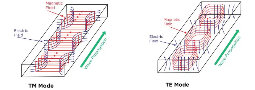
The mode of propagation in transmission lines and waveguides, as identified, has similarities and differences in the way the electromagnetic wave travels. Transmission lines mainly support the TEM modes, in which the electric and magnetic fields are perpendicular to the direction of propagation. They are also applicable over a wide range of frequencies and for many applications like audio frequencies and radiofrequency communications. In contrast, waveguides support TE and TM modes, and for optical fibers, they also support the HE modes, which are restricted to the shape of the waveguide and the frequency and power requirements of the application. The selection of these modes is hence determined by the requirements of the application, such as the frequency and power of the signal, and due to their nature, rectangular waveguides are preferable for high power since they have low loss. The modes TE and TM specifically apply to rectangular waveguides, and they are thus appropriate for signals in the GHz range.
Materials and Fabrication
Materials Used for Transmission Lines
The choice of materials for transmission lines, whether it is coaxial cables, twisted pairs, or microstrip lines, is crucial for their performance, cost, and application. Coaxial cables usually have copper or aluminum as the core conductor because of the materials’ excellent electrical conductivity . In turn, the surrounding insulating layer, which is essential for signal loss and crosstalk prevention, is made of polyethylene or PVC , which is one of the ways to balance the performance and price aspects. Finally, the shielding layer is made of braided copper or aluminum to protect the signal from external electromagnetic interference . Ethernet-type or twisted pair cable is usually made of copper as well. The interior insulating material may be both ordinary PVC and it can be FEP in high-performance or high-temperature or chemical resistance applications. A microstrip line family is used in printed circuit boards and has copper for the signal path material and FR4 as the dielectric substrate material . PTFE is also applied for higher-frequency microstrip line applications. In summary, these materials are used for transmission lines to provide appropriate electrical performance and ensure that they are suitable for modern electronics in terms of performance and ease of fabrication.
Materials Used for Waveguides
Waveguides apply to microwave frequency components, and, thus, their materials should have low energy loss and be able to transfer electromagnetic waves efficiently . Rectangular and circular waveguide types are often made of low-resistive metals, such as copper or aluminum. The latter are used because aluminum is lighter and cheaper and copper, in turn, is their excellent conductor. The waveguide fabrication is essential for product function and appropriate wave transfer . Optical fibers, in turn, are specific and consist of silica glass or plastic in their core .
Fabrication Techniques for Transmission Lines and Waveguides
Coaxial cables are usually made by extrusion, with the core conductor becoming covered by the insulating material and then enclosed by a metallic shield . Overall, these techniques allow ensuring uniformity, which is especially vital for modern rapid development of electronics. Twisted pairs are, as the name implies, based on multiple wire twists placed into the jacket to reduce the electromagnetic signal effect and ensure optimal signal output along the cable’s length .
Finally, microstrip lines are fabricated using the same processes used for PCBs . The most known are photolithography and etching, as well as the LDS process, necessary for creating complex three-dimensional structures. In the case of waveguides, both are suitable and may be fabricated by casting or machining. During the fiber drawing, the material is pulled out of the preform to allow long and thin fiber formation, and the optical fibers contain the same materials with a lower loss reaction.
