Directionality in directional couplers refers to their ability to distinguish between forward and reflected signals, often exceeding 20 dB in directivity.
Table of Contents
Basics of Directional Couplers
Directional couplers are critical devices in RF and microwave engineering, allowing the sampling of signal energy without disturbing the signal significantly. In particular, they are used to route signals coming in different directions in different paths; this is particularly important in power monitoring and systems that rely on feedback. A directional coupler is a device that couples part of the electromagnetic power in a transmission line to a port so that it can be used in another circuit . An essential feature of its operation is its ability to separate forward and reflected power—a feature that is useful in applications such as power measurement, signal sampling, and feedback systems. The main purpose of a directional coupler is to measure forward and reflected power; accordingly, it is a critical component in the optimization of RF systems.
Key Components
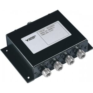
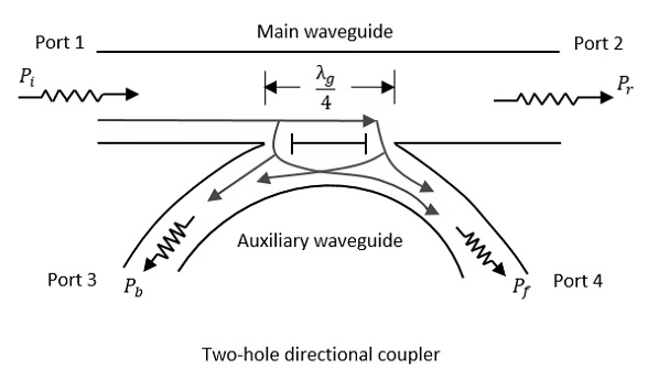
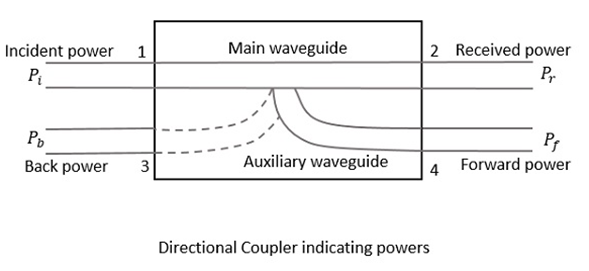
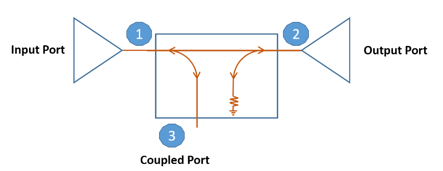
A directional coupler consists of four ports : an input port , an output port , a coupled port , and an isolated port . The choice of material and the design of these components are vital for the performance characteristic of the coupler, in particular, its insertion loss and directivity. For instance, in high-frequency applications, the coupler may be made of PTFE because of its lower dielectric loss at microwave frequencies . The coupling factor, which is a measure of how much of the input power is directed towards the coupled port, generally ranges from -20 dB to -3 dB . As a result, the coupled port will see a small proportion of the input power, varying from as low as 0.1% to as much as 50%. The principle of directionality relies on the constructive and destructive interference of waves. Specifically, the directional coupler is designed so that the signals travelling in one direction are combined constructively at the coupled port while the signals traveling in the other direction are either combined destructively or sent to the isolated port.
The directivity of the coupler can vary significantly; in higher-quality devices, it usually exceeds 30 dB. This means that more than 99.9% of the power from the forward signal is coupled whereas the power of the reflected signal is not. It is evident that the construction of a certain component and the materials it is made from dictate the characteristics of the coupler and, in turn, the trade-offs between loss, cost, size, and power handling, among other factors. The material affects the insertion loss of the coupler; on the other hand, it may affect its lifespan and reliability as well. Accordingly, it can be expected that a high-performance coupler designed for a life-critical low-volume application will make certain that its material and construction are in the perfect balance between loss, directivity, and power handling, even if the price should not be a constraint.
Types of Directional Couplers
Directional couplers vary by construction and application demands that they serve. Especially notable is the number of ports and the applicable transmission medium, with each distinction offering unique advantages and design considerations. In terms of the number of ports, the two types of directional couplers are 2-port and 4-port devices. 2-port directional couplers are simple and consist of a single path of an input signal and another path for the coupled signal. The major advantages of this type of couplers are their compact size and low cost, with their simplicity being useful in a variety of applications that are designed purely for signal sampling or injection . The 4-port directional couplers offer a more complete solution, with an additional isolated port and a transmitted port accompanying the typical input and coupled ports. In this capacity, they allow the measurement of both forward and reflected power, making them vital to applications that demand a high degree of power monitoring and control . The primary advantage of 4-port couplers is their ability to distinguish between the two signals with high precision, with most devices rated at 20 dB of directivity or more . In terms of raw power, this means that 4-port directional couplers can isolate over 99% of the power in the forward direction, making them ideal for applications that require precise power measurements and the ability to protect sensitive electronic devices from excess signal strength.
In terms of the transmission medium, the three types of directional couplers are stripline, microstrip, and waveguide. Stripline directional couplers benefit from a symmetrical strip of metal, usually copper, that is surrounded by two ground planes on both sides . Most notable is their application over a large frequency range, making them ideal in broadband applications. The electromagnetic field distribution is also uniform, which allows for consistent coupling levels over the full range of operation. Microstrip couplers only use a single thin strip of metal on one side of a grounded substrate . The benefits of this type of transmission medium are its ease of fabrication and integration into PCBs, which makes it very cheap to manufacture. However, it results in a high insertion loss and low power handling ability, with its performance in terms of these factors being inferior to striplines but superior to waveguide couplers. Waveguide transmission medium uses hollowed-out cross sections of metal to guide electromagnetic waves, with their most notable application being high-frequency and high-power environments by allowing signals to travel within a metal-filled enclosure .
Operational Principles
The formation and operation of directional couplers are central to their selective signal routing, a feature that is essential for a variety of RF and microwave applications. As such, the presented content focuses on the mechanism behind the devices’ operation and their key parameters, as well as the role of certain materials and the development of new options in determining overall impact.
Coupling Mechanism
A coupling mechanism refers to the arrangement or part of the work mechanism between two transmission lines that allows a portion of the electromagnetic energy in one line to pass to the other. The established level of coupling is then retained and can be classified based on the materials and designs used and what frequencies it is intended to or capable of working with thereafter. For example, in typical designs seeking to achieve -10 dB coupling, the amount of power sent from the main line to the coupled is 10%, while the other 90 continues to the output . The extent to which this transfer is precise is vital as it allows for the effective measurement of the signal strength without significant interference in the main line.
Isolation and Directivity
Isolation for a directional coupler refers to its ability to keep energy from traveling in reverse from the output or coupled port to the input port . High values of isolation are critical, although the corresponding low values of reflection are often presented for convenience. A high-quality, typical directional coupler can have isolation levels in the region of greater than 30 dB, signifying that less than 0.1 % of the power from the coupled or isolated is shown to be reflected at the input . Directivity is calculated using these same measures, with high values, above 20 dB for decent quality couplers, ensuring minimal intervention between the transfer of forward and reverse waves. This parameter varies similarly based on the coupling region’s specific design and the materials used to build it.
The isolation and directivity values of a directional coupler depend on its design and are facilitated by specific production methods or materials. Advances in materials science, for instance, have led to the formation of substrates that can induce strong magnetic fields made of appropriate materials. Such advancing methods and strategies mean that directivity and isolation are improved, allowing for a tighter and more effective charge transfer over a longer lifespan in a smaller package. The overall performance of the couplers is defined by these various factors, with their isolationism and directivity increasing from changes to materials and production process. Such changes can also affect their insertion loss, which is also positively impacted, resulting in lower power loss, greater efficiency, and the potential for a longer lifespan but higher costs due to access and production.
Directional Coupler Design
The design of directional couplers is an intricate process that requires balancing many factors in order to meet specific application requirements. This balance is maintained by selecting appropriate materials and geometric configurations of the coupler. First, engineers must determine the operational frequency range, power handling capability, and the needed coupling level of the coupler. The first specification is essential because the coupler must work within the frequency band in question – for instance, a high-power radar system that can only operate at a particular frequency range. Power handling should be sufficient to withstand the level of power involved, and even mitigate a portion of it. Coupling is the required proportion of input power that goes to the coupled port of the coupler . In applications where the output must be identical to the coupled port, a -3 dB coupler is used, as it distributes power equally to the output and coupled ports. When only 1% of the signal must go to the coupled port in the application, as in signal sampling, a -20 dB coupler can be used.
A specific material determines a directional coupler’s characteristics and performance metrics – these include insertion loss, directivity, and power handling capability. Superior materials may be used to reduce power loss through the coupler, such as low loss dielectrics and superconductors . Insertion loss is generally below 0.1 dB at the highest frequency, thanks to the use of advanced materials with low dielectric constants. Thus, the use of advanced materials can decrease the coupler’s losses by hundreds of times and make the system considerably more effective overall. The geometry of the coupler is also integral in its proper function. The size and layout of the main and coupled lines as well as the type and distance of the isolating element and connectors is carefully selected to maintain the characteristics of the coupler across the frequency range.
For instance, the distance between the main and coupled line of the coupler determines its coupling level – they should be closer in the high-level coupler, but further in the low-level variety. Finally, human-designed couplers always make use of some feedstock, typically slabs and rods with known dielectric constants and properties. These elements are designed by our EMC engineers, who use electromagnetic simulation tools like Ansys or AWR to perform many design iterations to achieve the best performance-cost-size tradeoff. The geometry also limits the size of the coupler in the main line – the size of a coupler is directly linked to the wavelength and increases with reduced frequency. The design of couplers such as the ones described above not only led to ever-improved performance metrics such as efficiency and reduced losses, but these achievements also go hand in hand with increased cost and manufacturing complexity. Therefore, engineers must strike a balance between superior performance and practicality during the design phase.

