Table of Contents
Coaxial Probe Feed
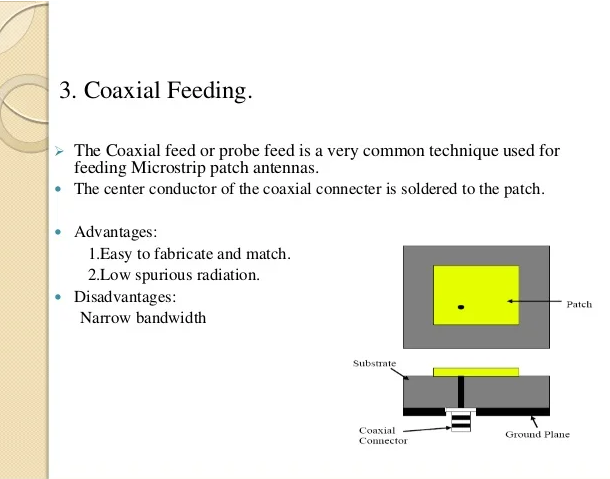
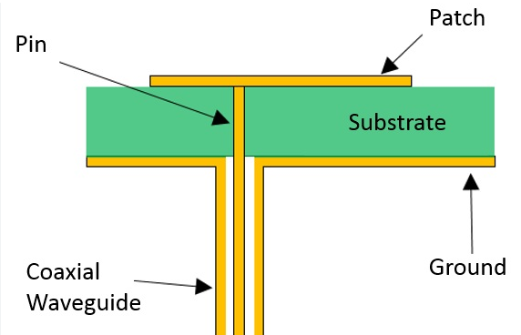
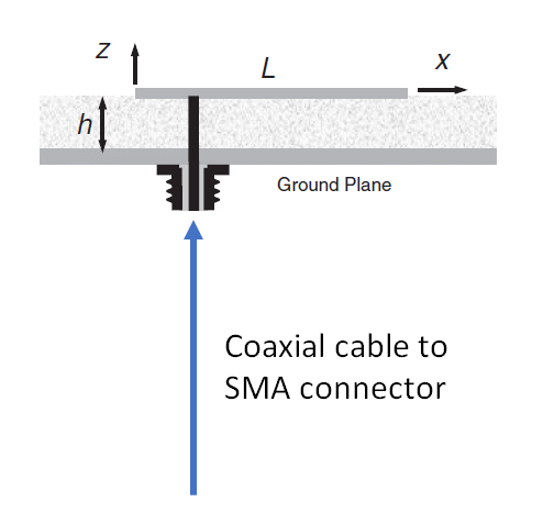
A coaxial probe feed is a popular method used in antenna design, particularly in patch antennas. It is based on the use of a coaxial cable that is attached directly to the radiating element. This technique is known for being simple while the impedance matching with the device is good. The implementation of this method consists of inserting a radiating patch with a microstrip feed line into a conducting medium through a coaxial probe.
Advantages:
-
Simplicity – the coaxial probe is easily installed in the whole structure.
-
Good bandwidth – it is sufficient to implement coaxial probe feed to have a band of approximately 10% in the system.
-
Good impedance matching is essential for antenna efficiency. The matching can be adjusted by properly varying the probe position and the coaxial cable dimensions.
Design criteria:
-
Probe position – to find the optimal area of impedance matching, the coaxial probe should be located in the vicinity of the radiating patch’s edge. It allows to find the optimal impedance matching due to the intuitive choice of the probe place.
-
Coaxial cable dimensions – the key criteria are the radii of the inner and outer conductors of a cable. The quality of the antenna is stipulated with these dimensions.
-
Type of connection – the connector implemented with the coaxial probe is selected to reduce the loss of the system and simplify the stability of the connection.
Applications are the following:
-
In wireless communication, such as routers, mobile phones, satellite communication systems, etc.
-
Due to the directivity of the antenna, the most efficient place for their implementation is radar systems. These systems monitor the aviation or maritime situation.
Cost analysis is also relatively simple. The price of a high-quality coaxial cable varies from $0.50 to $3.00 per foot . Due to the aluminum foil implementation for 100% signal coverage, there is a significant available volume of products. As a buyer can purchase a significant quantity, the costs will be minimal. The implementation of new materials and loading with various coatings might considerably reduce the cost of manufacturing.
Design Considerations for Coaxial Feed in Antennas
Designing antennas with coaxial feed requires considerations of various factors, which impact performance and operation of the antenna in a communication system. I studied and researched the following considerations that are important for the design of such antennas:
Impedance Matching
Critical for Efficiency: Impedance matching determines the efficiency of power delivery from the transmission line to the antenna. If the coaxial feed is not matched to the input impedance of the antenna, which depends on the antenna design and is typically around 50 ohms, there will be a significant loss of power and efficiency of radiation.
Adjustment Techniques: Adjusting the impedance can be achieved with help of quarter-wave transformers or tuning stubs placed on the coaxial cable .
Cable Selection
Impact on Losses: The cable selected for the coaxial feed has a significant impact on performance in terms of losses and bandwidth.
Typical Specifications: For example, RG58 cable has an attenuation of about 0.2 dB per meter at 100 MHz, while RG213 has an attenuation of about 0.1 dB per meter . The lower loss of the second option makes it more preferable for the antenna design.
Connector Considerations
Importance of Reliable Connection: The connection between the coaxial feed and the receiver should be reliable in order to minimize the potential signals losses and attenuation of radiation.
Common Connectors: There are two common options that are the most suitable for this connection – SMA and N-type connectors. They are suitable for the broad range of frequencies and are mechanically robust.
Positioning of the Feed
Influence on Radiation Pattern: The coaxial feed is typically located at the point of the antenna element, such as a patch or a dipole, at which the electric and magnetic fields of the desired mode are maximized. It also needs to be positioned at the point at which the feed matches the impedance.
Optimization Techniques: The desired position is determined using either simulations or experiments.
Environmental Considerations
Durability: It needs to be protected from the environment given exposure to moisture, temperature changes, and ultraviolet radiation.
Materials Used: Polyethylene is a good dielectric for the cable jacket, and gold, silver or another noble metal is preferred for the receiver.
Microstrip Feed
Introduction
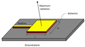
Microstrip feed is one of the most popular feeding techniques that are applied in antenna design. The primary feature of the method is the application of a microstrip line to feed the radiating element. At the same time, the radiating element is the service area of the antenna, instantly converting the electromagnet energy into the volume wave, letting it be fed to the transmitter or the receiver. Since the microwave can be reradiated due to the Ohm law, the radiation is proportional to the current flowing in the element. In such a way, the microstrip feed is relevant since it is applied in one of the most economically feeding technique. The feed made using microstrip line is used in the way that microwave actions are in the z direction^1. The most common antennas which use the microstrip feed are patch antennas.
Advantages of Microstrip Feed
One of the advantages of the microstrip feed is that anteshaving such feeds are light and take less space. As a result, they interfere less with the style and appearance of the object to where these antennas can be previously integrated. They weigh less and can be used for satellites cameras^1.
Design Considerations
Among the critical design consideration of microstrip feed is the fact that the stripe and the radiating element should have a good impedance match, which results in the effective transferring of the power. Additionally, the design is highly affected by the substrate’s material. Such common material as 3mm FRS, having materials dielectrical constant 4.5, or Rogers has a dielectric constant of 2, operated at 10 GHz, has great potential. What is more, it is important to think about the size, as the biggest size applied for microstrip feed is equivalent to the official wavelength. This match frees half the strength, which makes it possible to reach highly efficient antennas.
Line losses are critical to consider, as these losses are determined by the dielectric residue in the substrate. Coincidentally, with the line losses, dielectric residue is quantified from the equation:
Where ∵ = e-1. In such a case, the loss of energy in the line is:
Applications
Microstrip feed antennas are widely applied, some of the examples are provided below:
-
Communication: there are many wireless mobile devices, wifi routers, etc.
-
Aerospace and military: lots of materials are on demand.
-
More thereafter, a lot of other antenna ground antennas can be constructed using microstrip feed.
Challenges and Solutions
Challenges
There are two major challenging issues that, at the same time, can change in a doubleway the feeder efficiency. The first one is that the line itself can carry mechanical energy as surface waves. The feeder has a ripple in the substrate, which, to some extent, reflects these big waves such as edge plasmons that have much higher speed than those in the center of the line or have lower ripple-based structures^1. The other tracks that can reduce antenna feeder efficiency is having the frequency of the antenna effect or that big bandwidth that can change because of the feed. A microstrip feed antenna can only cover the microwave band. This can be limited by building a thicker size that results in a wide Q of about 10 to 50, or using parasitic margin elements that require time as a reflector. What is more, in the future, it is possible to integrate this kind of feeder into a 5G, IOT, or mmWave.
Waveguide Feed
Waveguide feed is a way to feed an antenna widely used in high-frequency applications, such as radar, satellite communication, microwave systems, and others. This type of feed uses a waveguide – a hollow tube made of metal, known for guiding electromagnetic waves from the transmitting antenna or from the transmitted signal to the feeding antenna. The main advantages of waveguide feed include the low loss, the ability to handle a high level of power , providing a wide bandwidth, and weight efficiency.
Design parameters include the waveguide’s dimensions, such as height and width, determining the frequency range it can be used for. For instance, WR-90 waveguide is used for the 8.2- to 12.4-GHz band . The mode of propagation within the waveguides, such as TE and TM modes, also impacts the efficiency and the bandwidth of the feed system. The material can be chosen between different types of metals, such as copper and aluminum, providing excellent conductivity and low loss. The manufacturing method may influence the cost, as some systems, such as extruded or cast waveguides, are cheaper.
The most important applications of the waveguide feed system are radar, satellite communication, and microwave systems. Radar systems used for aircraft, ships, and even cars, require high power and low loss provided by the waveguides. They are also used for satellite communication, where their low loss is critical to ensure a strong signal. In microwave systems, the waveguide is used in the terrestrial microwave link between two base stations.
The major challenges are connected to the size and the weight, which can be addressed by finding alternative materials and more efficient manufacturing methods. Although the future of waveguide feed systems is not certain, as technology is expected to develop smaller and more advanced devices, the ability to support higher frequencies and more complex modulation schemes should determine the new uses of these systems with the advancement of 5G and possible 6G.

