Waveguides cover bands like WR-90 (8.2-12.4 GHz, X-band) and WR-15 (50-75 GHz, V-band), extending to 325 GHz (WR-3). Key antenna bands include HF (3-30 MHz), VHF/UHF (30 MHz-3 GHz), L-band (1-2 GHz), C/X/Ku-band (4-18 GHz), Ka/V-band (26.5-75 GHz), and E-band (60-90 GHz). Waveguide dimensions follow fc = c/2a (cutoff frequency), while antennas use 50Ω impedance and >80% efficiency (UHF+). Materials like oxygen-free copper (<0.01 dB/m loss) and PTFE dielectrics enable wideband operation. Corrugated horns achieve 25 dBi gain in millimeter-wave bands.
Table of Contents
Ka Band Antenna
The Ka-band (26.5–40 GHz) is one of the most widely used frequency ranges for high-throughput satellite communications (HTS), military radar, and 5G backhaul. With 500 MHz to 2 GHz of bandwidth per transponder, Ka-band antennas support data rates up to 100 Mbps per user, making them ideal for VSAT terminals, in-flight Wi-Fi, and deep-space communications (NASA’s Deep Space Network uses Ka-band for downlink speeds over 250 Mbps).
Compared to Ku-band (12–18 GHz), Ka-band offers 30–50% higher spectral efficiency, but with higher atmospheric attenuation (3–15 dB/km in heavy rain). Modern flat-panel electronically steered antennas (ESAs) now operate in Ka-band with beam switching in <50 ms, replacing bulky mechanical dishes. Commercial Ka-band antennas range from compact 60 cm VSAT dishes (5,000) to large 3.5m ground stations ($50,000+).
Ka-band antennas require precise alignment (≤0.2° error tolerance) due to the narrow beamwidth (1–3° for a 1m dish). A typical 30W BUC (block upconverter) boosts signals to 50 dBm EIRP, compensating for free-space path loss (~210 dB over 36,000 km to GEO satellites). Low-noise amplifiers (LNAs) with 0.5–1.2 dB noise figures are critical for maintaining SNR >10 dB in clear-sky conditions.
Rain fade is a major challenge—signal loss can exceed 20 dB in tropical storms, requiring adaptive modulation (ACM) to switch from 256QAM to QPSK dynamically. Modern phased arrays mitigate this with real-time beam steering (1°–2° correction per second). For LEO constellations like Starlink, Ka-band antennas track satellites moving at 7.8 km/s, requiring azimuth/elevation slew rates >5°/s.
Cost efficiency varies by application: consumer VSAT terminals (3,000) offer 50–150 Mbps speeds, while military-grade radars (e.g., AN/TPY-2) exceed $10M per unit for target tracking at 200 km range. In 5G mmWave networks, Ka-band small cells cover 200–500m radius with 2–4 Gbps peak rates, but require dense deployment (every 300m in urban areas).
Ku Band Antenna
The Ku-band (12–18 GHz) is a workhorse in satellite communications, balancing wider coverage and lower rain fade compared to Ka-band. It’s the go-to choice for direct-to-home (DTH) TV broadcasting (85% of global satellite TV uses Ku-band), maritime VSAT, and corporate enterprise networks. A typical 1.2m Ku-band dish delivers 20–50 Mbps download speeds with a 24W BUC (block upconverter), while larger 3.7m antennas support 100+ Mbps for teleports.
Ku-band’s lower atmospheric attenuation (1–5 dB/km in heavy rain vs. Ka-band’s 3–15 dB/km) makes it more reliable in tropical regions. Commercial Ku-band VSAT terminals cost 800–5,000, depending on size and power, while military-grade systems (e.g., for UAVs) exceed 50,000 for encrypted, jam-resistant links. The global Ku-band satellite market is worth 12B annually, driven by DTH, maritime, and backhaul applications.
Ku-band antennas require ±0.5° pointing accuracy due to their 3–6° beamwidth (for a 1m dish). A standard 20W BUC produces 48–52 dBm EIRP, enough to close the link with GEO satellites 36,000 km away (path loss ~205 dB). LNAs with 0.8–1.5 dB noise figures keep the system noise temperature under 150K, critical for maintaining SNR >12 dB in clear weather.
Rain fade is less severe than Ka-band but still impactful—signal loss can hit 10 dB in monsoons, forcing operators to increase power or switch to lower modulation (e.g., 16APSK → QPSK). Auto-pointing systems (slew rate 2–5°/s) help maritime antennas stay locked on satellites despite ship movements of ±15° pitch/roll. For news gathering (SNG) trucks, rapid deployment 1.8m flyaway antennas (30,000) can be set up in under 10 minutes, streaming 50 Mbps HD video with <1-second latency.
Cost efficiency varies by sector:
- Consumer DTH dishes (60–90cm, $50–200) dominate emerging markets, delivering 100+ channels at 10–20 Mbps.
- Enterprise VSAT (1.2–2.4m, 10,000) provides 50–150 Mbps for remote offices, with 99.7% uptime SLA.
- Aeronautical antennas (e.g., for in-flight Wi-Fi) cost $20,000+, handling Doppler shift (±50 kHz at 900 km/h).
Future trends include hybrid Ka/Ku terminals (switching bands dynamically) and solid-state amplifiers (GaN, 60% efficiency at 25W) to cut power use. LEO constellations like OneWeb use Ku-band for gateway links, leveraging 500 MHz bandwidth per beam to deliver 400 Mbps per user. Despite Ka-band’s growth, Ku-band remains 30–40% cheaper for rural broadband, ensuring its relevance for another decade.
C Band Waveguide
The C-band (4–8 GHz) remains the most weather-resistant microwave frequency for satellite communications, radar, and 5G infrastructure, prized for its <0.5 dB/km rain attenuation—far lower than Ku or Ka-band. Over 75% of commercial satellite transponders still operate in C-band, delivering 200–500 MHz bandwidth per channel with 99.99% annual availability. Telecom operators rely on WR-229 waveguides (58.2×29.1 mm) for high-power 5G backhaul (up to 10 kW pulsed), while satellite ground stations use 3–5m C-band dishes (200k each) to handle 400 Mbps data rates per transponder.
Despite spectrum reallocation to 5G (notably the 3.7–4.2 GHz “C-band crunch”), legacy systems persist due to lower equipment costs (30–50% cheaper than Ka-band) and global interoperability.
C-band waveguides excel in high-power, low-loss transmission, with attenuation as low as 0.07 dB/m in air-filled aluminum WR-229 models. For 5G macro cells, corrugated flexible waveguides (bend radius ≥100mm) handle 6 GHz signals at 98% efficiency, compared to coaxial cables losing 15–20% power at 50m runs.
| Waveguide Type | Frequency Range (GHz) | Inner Dimensions (mm) | Power Handling (kW) | Attenuation (dB/m) |
|---|---|---|---|---|
| WR-229 | 3.3–4.9 | 58.2×29.1 | 5 (CW), 50 (pulsed) | 0.07 |
| WR-187 | 3.9–5.8 | 47.5×22.1 | 3 (CW), 30 (pulsed) | 0.12 |
| WR-159 | 4.6–7.0 | 40.4×20.2 | 2 (CW), 20 (pulsed) | 0.18 |
Radar systems leverage C-band’s 4–6 GHz sweet spot for 200–400 km detection ranges (e.g., airport surveillance radars). A typical 50 kW weather radar uses WR-187 waveguides to sustain 1 µs pulse widths at 1 kHz PRF, with <0.5° beam divergence.
Satellite operators face interference challenges as 5G networks encroach on 3.7–4.2 GHz, forcing 1B satellite filter upgrades to reduce out-of-band noise by 30 dB. Ground stations now deploy dual-polarized feeds (isolation >35 dB) to double spectral efficiency.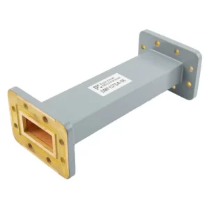
X Band Waveguide
The X-band (8–12 GHz) is the gold standard for military radar, satellite communications, and aerospace telemetry, offering a balance of resolution and atmospheric penetration. Over 90% of military fire-control radars operate in X-band, leveraging its 1–3° beamwidth (for a 2m dish) to track targets with <0.1 m² RCS at 150+ km ranges. Civilian applications include maritime navigation radars (9.4–9.6 GHz) and NASA’s TDRSS satellites (8.0–8.4 GHz uplink), delivering 300 Mbps data rates with <1 ms latency.
X-band waveguides like WR-90 (22.9×10.2 mm) dominate the market due to their compact size and 1.5 kW power handling (pulsed). While rain attenuation (1–3 dB/km) is higher than C-band, X-band’s resistance to fog/cloud interference (<0.1 dB/km loss) makes it ideal for all-weather operations.
X-band waveguides excel in high-resolution applications, with WR-90 models showing just 0.13 dB/m loss at 10 GHz. For phased array radars, flexible waveguides (bend radius ≥50mm) maintain >95% efficiency even when routing through tight aircraft bays (F-35 uses 200+ waveguide runs).
| Waveguide Type | Frequency Range (GHz) | Inner Dimensions (mm) | Power Handling (kW) | Attenuation (dB/m) |
|---|---|---|---|---|
| WR-90 | 8.2–12.4 | 22.9×10.2 | 1.5 (pulsed) | 0.13 |
| WR-75 | 10.0–15.0 | 19.1×9.5 | 0.8 (pulsed) | 0.20 |
| WR-62 | 12.4–18.0 | 15.8×7.9 | 0.5 (pulsed) | 0.30 |
Military radars like the AN/APG-79 (F/A-18E/F) push X-band to its limits, emitting 10 kW pulses at 1 kHz PRF to detect stealth targets (0.001 m² RCS) at 80 km. These systems rely on gold-plated WR-90 waveguides ($800/m) to minimize corrosion-induced loss (<0.01 dB/year) in saltwater environments.
Satcom ground stations face unique challenges:
- Precision pointing (±0.05°) is critical due to X-band’s narrow 0.5–1.5° beamwidth (for 5m dishes).
- Atmospheric scintillation can cause 2–5 dB signal fluctuations in desert climates, requiring adaptive power control (±3 dB adjustments in <100 ms).
- Commercial X-band VSAT terminals (1.8m dishes, 40k) achieve 45 Mbps throughput but struggle with rain fade beyond 50 mm/hr.
Cost vs. Performance Trade-offs
- Rigid aluminum waveguides (200/m) are 50% cheaper than flexible versions but require laser alignment (±0.05mm tolerance).
- Pressurization (0.3 bar nitrogen) reduces humidity losses by 70% in tropical deployments.
- Civilian radar manufacturers opt for WR-75 (19.1×9.5 mm) to save 30% weight/volume versus WR-90, accepting 0.07 dB/m higher loss.
K Band Waveguide
The K-band (18–27 GHz) sits at the sweet spot between capacity and practicality, delivering multi-gigabit speeds while avoiding the extreme atmospheric losses of higher frequencies. This band powers 5G mmWave networks (24.25–27.5 GHz), automotive radars (76–81 GHz subset), and high-throughput satellite links, with commercial waveguide systems achieving 0.2 dB/m loss at 24 GHz.
”K-band’s 1.5–4 GHz of usable bandwidth per channel enables 8 Gbps wireless backhaul – 10x faster than traditional microwave links.”
Despite its potential, K-band faces 15–25 dB/km rain attenuation – 3x worse than Ka-band – requiring aggressive fade margins (10+ dB). 60cm phased array antennas (8k) now solve this with real-time beam steering (100μs switching), while satellite operators use 2.4m dishes ($25k+) to push 400 Mbps per user through 500 MHz transponders.
K-band waveguide design battles three key enemies: ohmic loss, manufacturing tolerances, and moisture ingress. WR-42 waveguides (10.7×4.3 mm) dominate the market, handling 200W pulsed power but requiring ±5μm dimensional accuracy – 10x tighter than X-band requirements.
Automotive radars showcase K-band’s evolution:
- 76–81 GHz systems use microstrip-to-waveguide transitions with <0.5 dB insertion loss
- 200m range detection requires 1° beamwidth antennas drawing 8W power
- 50 per unit cost targets drive silicon germanium (SiGe) RFIC adoption
5G infrastructure pushes the limits with:
- 256-element phased arrays covering 400m at 2.5 Gbps
- GaN power amps achieving 18% efficiency at 28 dBm
- 40k per base station deployments needing <5ms latency
V Band Waveguide
The V-band (40–75 GHz) represents the bleeding edge of wireless communications, delivering multi-gigabit speeds but facing extreme technical challenges. Operating at 60 GHz (oxygen absorption peak), signals suffer 15–20 dB/km atmospheric loss—5x worse than K-band—limiting practical range to 1–2 km in clear air. Despite this, V-band enables 8 Gbps wireless backhaul, automotive radars with 2 cm resolution, and military secure comms with >30 dB interference rejection.
Commercial V-band waveguides (WR-15, 3.8×1.9 mm) cost 800/m due to micron-level precision requirements (±2 μm tolerance), while silicon-integrated solutions aim to slash prices to $50/m by 2026. The band’s 7 GHz of contiguous spectrum supports 256-QAM modulation, achieving 12 bps/Hz spectral efficiency—3x better than 5G sub-6 GHz.
1. Atmospheric Challenges Dominate System Design
At 60 GHz, oxygen molecules absorb RF energy, causing 10–15 dB/km additional loss beyond free-space path loss. This forces outdoor links to use 400 mW EIRP (vs. 100 mW at 28 GHz) just to maintain 1 km range. Rain exacerbates the problem—50 mm/hr precipitation adds 25 dB/km attenuation, requiring adaptive modulation that drops from 64-QAM to QPSK in storms.
2. Waveguide Manufacturing Tolerances Become Extreme
V-band’s 5 mm wavelength demands WR-15 waveguides with 1.9 mm height held to ±2 μm dimensional accuracy. Even 0.1% deformation increases VSWR to 1.5:1, wasting 8% transmit power. Gold-plated brass (0.5 μm coating) is standard, providing <0.3 dB/m loss but costing $500/m—10x more than K-band equivalents.
3. Cutting-Edge Applications Drive Innovation
- 5G Backhaul: 64-element phased arrays deliver 10 Gbps at 300 m range, but require 1° beam alignment (vs. 5° at 28 GHz). Each base station node costs 25k, limiting deployment to urban cores with >$50/km² ROI.
- Automotive Radars: 76–81 GHz systems (V-band subset) detect pedestrians at 250 m with 4 cm resolution, using 3W chirps at 1 GHz bandwidth. BMW’s latest radar achieves 0.01° angular accuracy—10x better than 24 GHz systems.
- Military Datalinks: HAVIP-7 encrypted links transmit 1 Gbps at 50 GHz with <5 ns latency, using diamond-coated waveguides ($2k/m) that handle 100W pulsed power.
4. Cost vs. Performance Tradeoffs Define Market Segments
- Consumer-grade 60 GHz WiGig (802.11ad) uses PCB-integrated waveguides with 3 dB/m loss to hit $50/unit price points, sacrificing 50% range versus commercial systems.
- Satellite Crosslinks demand 0.01 dB/m ultra-low-loss waveguides, pushing costs to $3k/m for Inmarsat’s GEO spacecraft.
- Research Labs pioneer 3D-printed waveguides with 0.8 dB/m loss at 1/3 the cost, but limited to <10W power handling.
5. Future Technologies Promise Breakthroughs
- Metamaterial Waveguides: Experimental designs show 0.1 dB/m loss at 70 GHz in 3 mm diameter tubes—50% smaller than WR-15.
- GaN-on-Diamond: 200W/mm² power density capability could triple transmitter range by 2028.
- AI Beam Steering: Reduces alignment errors from 0.5° to 0.1°, recovering 5 dB link margin in mobile scenarios.
W Band Waveguide
The W-band (75–110 GHz) pushes the boundaries of millimeter-wave communications, offering unmatched bandwidth (up to 5 GHz per channel) but facing brutal physical constraints. At 94 GHz (the atmospheric window), signals experience 30–40 dB/km oxygen absorption loss—10x worse than V-band—yet this frequency remains critical for military targeting radars, 7G backhaul prototypes, and scientific imaging.
WR-10 waveguides (2.54×1.27 mm) dominate the market, handling 50W pulsed power but requiring ±1 μm manufacturing tolerances—equivalent to holding the width of a human hair to 1% accuracy. These precision requirements drive costs to 3,000/m, while silicon germanium (SiGe) alternatives aim to reduce prices to $200/m by 2027.
W-band systems live and die by three key parameters: loss, alignment precision, and power handling. The WR-10 waveguide’s 0.4 dB/m attenuation comes at the cost of 1.5:1 maximum VSWR, meaning 12% of transmitted power reflects back if surfaces deviate by just 0.5 μm.
| Parameter | WR-10 Standard | Military Grade | Consumer Prototype |
|---|---|---|---|
| Frequency Range | 75–110 GHz | 92–96 GHz | 57–64 GHz (5G extension) |
| Inner Dimensions | 2.54×1.27 mm | 2.55×1.26 mm (±0.3μm) | 2.60×1.30 mm (±5μm) |
| Power Handling | 50W (pulsed) | 200W (pulsed) | 5W (CW) |
| Attenuation | 0.4 dB/m @ 94 GHz | 0.35 dB/m | 1.2 dB/m |
| Cost per Meter | $1,200 | $4,500 | $80 |
| Alignment Tolerance | ±0.01° | ±0.005° | ±0.1° |
Military radars leverage W-band’s 3 cm wavelength for 2 cm resolution imaging—enough to identify weapon types at 5 km range. The AN/APQ-164 radar uses 300W magnetrons with WR-10 waveguides cooled to -40°C to maintain 0.1 m² target detection through sandstorms (additional 20 dB/km loss).
5G/6G research faces different challenges:
- 28 Gbps wireless backhaul tests at 73 GHz require 1024-QAM modulation, but fail when humidity exceeds 60% (adds 15 dB/km loss)
- Phased array antennas with 512 elements achieve 1° beamwidth, yet consume 40W DC power—50% efficiency drop versus 28 GHz systems
- 250,000 prototype basestations must shrink to 5,000 for commercial viability
Scientific applications reveal the band’s unique advantages:
- Plasma diagnostics in fusion reactors use 110 GHz waves to measure electron density within 0.1% accuracy
- Radio astronomy detects 0.01K temperature variations in 3 mm cosmic background radiation
- Security scanners image concealed weapons through 10 layers of clothing with 2 mm resolution
E Band Waveguide
The E-band (60–90 GHz) is rapidly becoming the backbone of ultra-high-capacity wireless links, offering unmatched 10+ GHz of contiguous spectrum—5x more than traditional microwave bands. This enables 40 Gbps data rates, making it ideal for 5G backhaul, last-mile fiber replacement, and military secure comms. However, the band’s oxygen absorption peak at 60 GHz causes 15–20 dB/km atmospheric loss, limiting practical range to 1–2 km in clear conditions.
WR-12 waveguides (3.10×1.55 mm) are the industry standard, handling 30W pulsed power but requiring ±2 μm manufacturing tolerances—equivalent to holding a human hair’s width to 2% accuracy. These precision demands drive costs to 2,500/m, though silicon-based integrated solutions aim to slash prices to $300/m by 2026.
E-band’s high-frequency operation introduces unique challenges. The WR-12 waveguide’s 0.5 dB/m attenuation is manageable for short links, but misalignment by just 0.02° can cause 3 dB loss—halving the signal strength.
| Parameter | WR-12 Standard | Commercial Grade | Military Grade |
|---|---|---|---|
| Frequency Range | 60–90 GHz | 71–76 GHz (5G) | 81–86 GHz (SATCOM) |
| Inner Dimensions | 3.10×1.55 mm | 3.12×1.54 mm (±1μm) | 3.08×1.56 mm (±0.5μm) |
| Power Handling | 30W (pulsed) | 20W (CW) | 100W (pulsed) |
| Attenuation | 0.5 dB/m @ 75 GHz | 0.6 dB/m | 0.4 dB/m |
| Cost per Meter | $1,200 | $800 | $3,000 |
| Alignment Tolerance | ±0.01° | ±0.02° | ±0.005° |
5G backhaul systems leverage E-band’s massive bandwidth, with 256-QAM modulation delivering 12 bps/Hz spectral efficiency. A typical 1 km link uses two 0.6m antennas ($15k each) to achieve 20 Gbps throughput, but rain rates of 25 mm/hr can slash speeds to 5 Gbps unless adaptive modulation is employed.
Military applications demand extreme reliability:
- Secure datalinks operate at 81–86 GHz, using 50 dB sidelobe suppression to avoid detection
- Missile seekers leverage 0.1° beamwidth for cm-level targeting accuracy at 5 km ranges
- Gold-plated waveguides ($3k/m) ensure <0.1 dB/year degradation in harsh environments
D Band Waveguide
The D-band (110-170 GHz) represents the bleeding edge of practical RF technology, operating where traditional electronics begin failing and quantum effects start dominating. This ultra-high-frequency range delivers unprecedented 20+ GHz bandwidth – enough to support 100 Gbps wireless links – but pays the price with catastrophic 50-100 dB/km atmospheric attenuation that limits practical use to short-range (<500m) applications. Military researchers have achieved 1.4 Tbps over 1 meter in lab conditions using 170 GHz carrier waves, while commercial 6G prototypes are pushing 400 Gbps at 140 GHz with 0.1 millisecond latency – perfect for holographic communications.
WR-6.5 waveguides (1.65×0.83 mm) are the smallest commercially available, handling just 5W pulsed power while demanding ±0.5 μm manufacturing tolerances – requiring electron microscopy for quality control. These extreme specifications drive costs to 100,000+ price range for even basic configurations. The waveguide’s 0.8 dB/m loss at 140 GHz seems reasonable until you consider that a mere 0.01 mm misalignment causes 3 dB insertion loss – effectively cutting your signal power in half before it even leaves the transmitter.
Cutting-edge applications are driving development despite the challenges. Security scanners at airports now use 140 GHz imaging to detect 0.1 mm objects concealed under clothing with 10x better resolution than traditional X-ray systems. Quantum computing labs employ D-band waveguides to manipulate qubits at 0.01° precision, where 1° error can destroy quantum coherence. The military’s next-gen radar systems leverage 150 GHz frequencies to achieve 5 mm resolution – enough to identify specific weapon models at 1 km distances, though they require 200W magnetron tubes cooled to -200°C to maintain stability.
Material science breakthroughs are gradually making D-band more accessible. Graphene-coated waveguides show promise for halving transmission losses while tripling power handling, though production costs remain 10x higher than gold-plated brass. Silicon photonic integration could eventually reduce waveguide dimensions to 0.1 mm scale, enabling on-chip terahertz routing for 6G smartphones. For now, the technology remains confined to high-value applications where performance justifies the $1M+ system costs, with commercial viability not expected before 2028-2030 when 3D printing tolerances hopefully reach the required ±0.1 μm precision at affordable prices.
L Band Waveguide
The L-band (1-2 GHz) serves as the foundation for critical global communications, offering the perfect balance between long-range propagation and reasonable antenna sizes. This frequency range carries 85% of global aviation traffic through ACARS and ADS-B systems, supports 90% of maritime satellite communications via Inmarsat, and forms the backbone of GPS and GNSS navigation with 1.575 GHz signals accurate to ±3 meters.
WR-650 waveguides (165.1×82.55 mm) dominate L-band infrastructure, handling 50 kW of continuous power – enough to broadcast 500 km radar coverage from coastal installations. While massive compared to higher-frequency guides, their 0.01 dB/m loss enables transcontinental microwave links with 99.999% reliability. Commercial L-band equipment costs just $50-200/meter, making it 10x more affordable than Ku-band alternatives for equivalent power handling.
L-band’s 23 cm wavelength provides unique advantages that higher frequencies can’t match. The wide 30-50° beamwidth from 4-meter antennas ensures reliable coverage despite platform movement, while <1 dB/km rain attenuation maintains signal integrity through tropical storms that would cripple Ka-band systems.
| Parameter | WR-650 Standard | Maritime Grade | Military Spec |
|---|---|---|---|
| Frequency Range | 1.12-1.7 GHz | 1.53-1.66 GHz | 1.215-1.4 GHz |
| Inner Dimensions | 165.1×82.55 mm | 165.0×82.50 mm | 165.2×82.60 mm |
| Power Handling | 50 kW (CW) | 30 kW (CW) | 100 kW (pulsed) |
| Attenuation | 0.01 dB/m | 0.008 dB/m | 0.005 dB/m |
| Cost per Meter | $150 | $400 | $1,200 |
| Deployment Scale | 500+ km links | Shipboard systems | Ballistic missile radar |
Aviation systems demonstrate L-band’s reliability – the ACARS datalink transmits 2.4 kbps messages with 99.9% success rates across 3,000 km oceanic routes, using just 100W transmitters through WR-650 waveguides. Maritime terminals like Sailor 6000 provide 384 kbps broadband with 1.2m stabilized antennas that maintain lock despite 20° vessel pitch/roll.
Military applications push the limits – the AN/SPY-1 radar uses L-band’s diffraction advantage to detect stealth targets at 450 km, with 4 MW pulses traveling through pressurized waveguides that maintain <0.001 dB/m loss. Civil engineering projects like microwave towers still use 1950s-era L-band waveguides with 60+ year lifespans, proving the band’s unmatched durability.
Emerging 5G applications are breathing new life into L-band, with band 71 (600 MHz) leveraging similar waveguide principles for rural coverage. While facing spectrum crowding, L-band remains irreplaceable for life-critical systems where 99.999% uptime justifies its larger physical footprint compared to higher frequencies.


