Table of Contents
Types of Standard Microwave Waveguides
Rectangular Waveguides
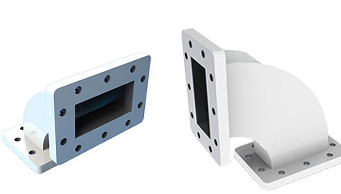
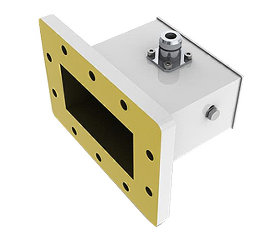
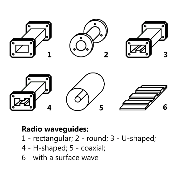
The most common waveguides are rectangular ones due to their vast advantages in microwave engineering in terms of simplicity and ease of manufacturing. This type can support TE and TM modes, but the dominant one is TE10 mode, as it ensures clad-to-clad radiation of electromagnetic energy in the structure . The typical ratio of the width and height of the cross-section is 2:1, as it gives the best optimized solution with the possibility to use more of the material to maintain the conditions of power handling. The rectangular waveguides have a bandwidth of about 30 percent of the center f, which makes them appropriate to use for narrow-band implementation .
Power Handling and Dimensions
The waveguides can handle tens of kilowatts of power at lower microwave frequencies. The WR-90-2.2.86 waveguide, for instance, has dimensions of 22.86 mm by 10.16 mm and can be used at 8.2 to 12.4 GHz.
Aluminum is the most popular material to manufacture waveguides due to its low cost, low density, and good electrical conductivity. However, in most cases, there is an extra layer of copper or silver to decrease the surface resistance.
Circular Waveguides
Circular waveguides are traditionally used, as the name indicates when the polarization of the transmitted wave is either circular or must be converted to such. The circular geometry is required in cases where the polarization needs to be rotated on a system or signal that only needs arches or is an alternative to a system in which the waveguide will be twisted or bent. This type can support a wider range of modes as compared to the rectangular geometry: TE, TM, and TEM. The bandwidth of the waveguide is equivalent to that of the rectangular type but is more effective.
The circular waveguides’ dominant mode is TE11 mode, and the efficiency varies greatly in relation to its counterpart due to symmetry linear polarization can be converted to circular or vice versa. It is also necessary in the dome of the dielectric lens, used in radar and satellite communication systems.
Dimensional Flexibility and Applications The diameter of circular waveguides ranges from a few millimeters to a few centimeters depending on the frequency of operation . This dimensional flexibility brings in a wide range of applications, from medical imaging to moon communication . Elliptical Waveguides
Elliptical Waveguides are unique for their mode stability, and polarization handling . They are widely used in the applications where the linear polarization needs to be maintained for long ranges, such as in telescope feeds and satellite communication and scanning . Mode Stability and Polarization The major benefit of the waveguides is maintaining the polarization of a signal transmitted and minimal distortion. This is essential for applications that require a highly linear signal such as, telescope feeds. It also shows lower modal dispersion, meaning overall signal retention . Manufacturing Complexity and Cost Elliptical Waveguides are more difficult to manufacture than rectangular and more expensive. They more widely produced than flexible waveguides of high performance. Flexible Waveguides
They are usually constructed by helical winding of a metal strip. Waveguides feature many degrees of freedom for movement. They are employed in the microwave parts of the system that have to be moved and connected. In the radar systems, satellite dishes, Coude feeds, this type of waveguides is completely essential. Flexibility and Power Handling Offering near-perfect flexibility, these waveguides lack power-handling ability due to the technique of production. As such, they are typically used in low to medium power applications, being able to use from a few watts up to several hundred. Cost and Application Since flexible waveguides are relatively complex, they cost more to make without compromising transmission quality. Nevertheless, they are of high importance in the applications mentioned where mechanical flexibility is required.
Fundamentals of Microwave Waveguide Design
Wave Propagation Modes
The mode of propagation determines how the electromagnetic wave will travel along the waveguide. TE and TM modes first two are the main ones. TE modes have the electric field component perpendicular to the direction of wave propagation. Similarly, TM modes have the magnetic field component perpendicular to the direction of wave propagation of the waves. The choice of mode has a significant effect on the waveguide properties such as the bandwidth of the waveguide and the power handling capabilities.
Dominant Mode and Bandwidth TE10 is the dominant mode of the rectangular waveguide, which makes it operate with a single mode and thus less lossy. The TE11 mode is the major mode for the circular waveguide; it has a larger bandwidth which makes the circular waveguide appropriate for the application. The power handling for the TE10 is higher than for the TE11 which makes it important for high power application. Mode Selection and System Design The choice of mode will vary with the application frequency of operation, power level, and the design of the system. The choice between circular spiral waveguide and the circular waveguide will depend on whether left or right polarization is required by the system Peak, 2011 .
Waveguide Dimensions and Frequency Range
The dimension of the waveguide is related to its frequency range of operation. Important waveguide dimensions need to be considered when determining the operation frequency below the cutoff frequency, and the wave cannot propagate. Dimension-Frequency Relationship The cutoff frequency is directly related to the width of a rectangular waveguide, the larger the width the lower the frequency of operation. The above relationship can be used in finding the dimensions of a waveguide with the WR designation, for example, WR-90 working on the 8.2 to 12.4 GHz frequency ranges. The dimensions of the waveforms an important component of the waveguide. It is therefore important to determine the proper dimension for a desired frequency range. Frequency Range and Application Suitability Different applications have different frequencies ranges of operation thus different waveguide sizes and types. For instance waveguides used in satellite communication systems are smaller because they use higher frequency ranges, which is the Ka-band (26.5 to 40 GHz). In the part that concerns waveguide selection, these smaller waveguides can be used in Wi-Fi applications which use 2.4 GHz ISM band. Material Considerations The choice of material used in making a waveguide will affect its efficiency, power handling and its cost of making. The sided materials include aluminum, copper, and silver. The later have some advantage over the former. Conductivity and Power Loss Silver and copper have high electrical conductivity which makes power losses and costs lower. The use of aluminum is an advantage as the weight of the waveguide will be lower also there cost, when used in the processing due to little effect of oxidation on the efficiency of the waveguide. Material Cost and Waveguide Performance Using silver coat over the copper or aluminum waveguide is similar to using pure silver which will reduce the resistive loss in the waveguide by reducing it’s surface rapture, hence, the cost of purchasing the material and the cost of processing waveguide material will be high but the performance of the waveguide will be improved.
Characteristics of Microwave Waveguides
Attenuation and Losses
In microwave waveguides, attenuation is the reduction in power of the wave as it progresses along the guide. The power losses in such microwave transmission lines can stem from conductor and dielectric losses as well as, to a lesser extent, from radiation losses. Conductor losses occur due to the finite conductivity of the waveguide walls, whereas dielectric losses arise from the fact that the insulators used in the waveguide absorb some of the microwave energy. Here, it can be noted that while silver has the best conductivity of all practical materials and thus exhibits the lowest conductor losses, the dielectric losses can be minimized by the use of air as the dielectric medium, that is, employing the waveguide without any dielectrics. Selecting materials accordingly with a lower loss tangent for the dielectric and higher conductivity for the conductors because of this significantly decreases the total attenuation. As a result, silver plating on a copper waveguide has this astounding characteristic of offering the least attenuation, meaning very little power can be lost while the wave traverses extensive distances.
Power Handling Capacity
The power handling capacity of a microwave waveguide is the highest power that can be carried by the guide without either causing any damage to the waveguide or effecting undue loss. This characteristic is affected by waveguide material, dimensions, and frequency. Copper waveguides are so widely used in microwave applications because they are good conductors of both electricity and heat and allow for relatively efficient heat dissipation. The only material that is a better conductor of heat than copper is diamond. Consequently, the capacity of a copper waveguide to handle higher power is greater than other metals. For example, aluminum is theoretically the best conductor of electricity known to man at room temperature and is also about one quarter the mass of a copper waveguide, which would make an aluminum guide ideal in terms of loss, yet aluminum waveguides cannot handle heat as well as copper can. Therefore, while copper waveguides are commonly in use, aluminum waveguides are usually limited to specialized and lightweight applications.
Dimensions are also a factor in this regard, considering that the larger the waveguide, the greater power it can handle. Furthermore, the capacity of the waveguide is considerably higher when the guide is capable of support modes with lower attendant attenuation. As an example, a WR-650 waveguide is virtually cubic in shape and measures 15.494 cm × 15.494 cm in width and 19.304 cm in length. With these much larger dimensions than smaller waveguides, WR-650s can handle kilowatts of power and are equal to massive radar installations.
Testing and Measurement for Microwave Waveguides
VSWR and Impedance Testing
Voltage Standing Wave Ratio is a measure of the match between a waveguide and a particular load on it, if the VSWR is 1, it indicates that their will be no reflection of whatever is being transmitted nor will there be any loss . For thick good-quality waveguides, the VSWR should be less than 0. creatively drawn transmission. Any Supporting reflections will transmit power back to the transmitter easily, this will in turn lead to the damage of the transmitter. In the case where the VSWR is 2:1 or more, more power will be lost because it will either go back to the transmitter causing damage or go back to the load in the process of damaging it. The gain of the connation, the input power overlooking, the scattered power and the standing wave inside the waveguide can be tested. This is done by measuring the impedance from the load end by measuring the variation of voltage with a variation in current.
Loss and Attenuation Testing
It is important to understand how much a particular waveguide can reduce or appear to reduce a signal that is passing through it from one end to the other end, then a particular measurement would be needed to test the attenuation in the waveguide. This can be measured by taking a measurement of the energy loss as the waveguide is guiding the propagation of the signal from one point of the guide to a distance away from that point. The optimum working practice will be from 0 to 50. This can be called the attenuation factor of the waveguide. The lower the attenuation the better the waveguide and anything below 0.5 is very good.
The material of the waveguide, the frequency it is tested at and also the surface treatment will have an effect on the amount of energy to lose as it is guiding a transmitted signal. Some waveguides are made of silver when used at the frequency of 10GHz it will have very low attenuation because it is made up of good conducting material and the surface finish and smooth.
Phase and Group Delay Testing
Phase delay is a measure of the time it takes for the waveforms to travel from the transmitting end to the receiving end. Phase is linear to frequency. A problem is only encountered when the waveforms are not together in the receiving end, which will cause different types of Signals together. The function is of the form . Group delay is a measure of the time differences between different frequencies signals.

