Table of Contents
N-Type Connector
The N-Type connector is a widely adopted solution in RF communication, combining durability, performance, and versatility. It is of special value for applications requiring stable, high-quality signal transmission in conditions of variable environmental impact. N-Type connectors are capable of handling high power levels, with typical ratings ranging from 200 to 1,000 watts, depending on the model. This makes them very suitable for high-power antenna systems, like those used in cellular towers, satellite communications, and broadcast stations. For example, in cellular base stations, N-Type connectors connect antennas that transmit signals in the power range of 100W to 500W to ensure reliable communication over long distances, even in inclement weather.
The frequency range of the N-Type connector spans from 0 GHz to 11 GHz, thus finding application in a variety of uses, including microwave and millimeter-wave systems. It finds applications in both commercial and military communications systems within this range. These connectors are specially appreciated because they provide low loss and stable performance in higher frequencies, which is very critical in applications such as radar systems and satellite communications. Compared to other types of connectors, like the BNC or SMA, an N-Type is capable of operating at higher frequencies and even at higher power. While a BNC connector typically handles frequencies up to 4 GHz and an SMA connector is rated up to 18 GHz, the N-Type’s ability to maintain signal integrity at frequencies above 10 GHz indeed makes it a go-for in more demanding applications.
Besides high power and frequency handling, the N-Type connector is highly durable. Being that the construction of this connector is robust, it is very common in outdoor environments. Normally, N-Type connectors are fabricated using brass, stainless steel, or nickel-plated brass, making them very resistant to corrosion. This resistance to corrosion is fundamental when the operating environment has moisture, salt, or extreme temperatures. For instance, cellular antennas mounted in coastal areas or on offshore oil rigs use N-Type connectors since they will not degrade from saltwater exposure. Many of these connectors are rated to IP67 or higher for environmental protection, meaning they are fully dust-tight and can operate after immersion in water to a depth of 1 meter for up to 30 minutes. This level of protection ensures that the connector maintains its performance in the harshest conditions.
The impedance of the N-Type connector is typically 50 ohms, which is the standard for most RF applications, but variants with 75-ohm impedance are also available for specific systems that require lower signal loss. The standard 50-ohm version is commonly used in most communication systems, including antennas for mobile phones, wireless networks, and television broadcasts. The Voltage Standing Wave Ratio (VSWR) for a typical N-Type connector is 1.1:1 or less, which is indicative of low signal reflection and high efficiency in signal transfer. With such low VSWR, the N-Type connector ensures that the signal transmitted from an antenna reaches the receiver with minimal loss, crucial for clear, uninterrupted communication in professional and high-stakes environments like air traffic control and military operations.
BNC (Bayonet Neill-Concelman) Connector
The Bayonet Neill-Concelman connector, or BNC, is one of the most common RF connectors, which is characterized by a reliable and easy-to-make and unmake secure connection. Applications include CCTV systems, test equipment, and audio and video transmission. A typical application for the BNC connector is 0 GHz to 4 GHz, thereby usually operating in a regular RF application. It can handle up to moderate power levels, with typical power ratings from 5 to 50 watts, depending on design. The BNC connector finds perfect application in low-power communication systems such as broadcast television and security cameras where medium-distance transmission of signals occurs without considerable loss of a signal.
The BNC connector is of a construction that makes installation and maintenance easy. The bayonet coupling mechanism is designed to be quick, secure, and easy to connect. The BNC connector has thus found its largest applications in places where a connector is often required to be connected and disconnected, like test and measurement systems. A simple twist-lock mechanism provides stability in the connection and makes it secure, even in slightly vibrating or mobile environments. The BNC connector is also far easier to deal with and requires much less torque when installing, which makes it ideal for DIY installations where time is critical.
The BNC connector normally has an impedance of 50 ohms, but this is one of the most common impedances used within RF communications. But 75-ohm versions are available for applications such as broadcast video, among other specialized systems. The 50-ohm BNC connector is applied widely in coaxial cable systems for LANs, video surveillance systems, and test equipment due to its low cost and ease of use. In terms of signal performance, the typical VSWR of a BNC connector is 1.2:1, which, although not as low as more specialized connectors like N-Type, still provides adequate signal transfer for most applications where high fidelity is not absolutely critical.
The maximum operating frequency of the BNC connector is often limited to 4 GHz, restricting its usability in higher-frequency systems, such as radar and satellite communications. However, for a wide range of applications, including video surveillance, CCTV, and signal testing, the BNC connector will be much more than sufficient. The relatively low frequency range of the BNC connector makes it unsuitable for high-speed data applications such as 5G communications or advanced radio systems, where higher frequency-rated connectors like the SMA or N-Type are preferred. However, BNC connectors are still widely used in older communication systems or systems with lower data rate requirements due to their cost-effectiveness and ease of use.
SMA Connector (SubMiniature version A)
The SMA can be defined as a subminiature version A connector, which is small and threaded RF connector that normally applies in high-frequency applications such as wireless communication, mobile devices, and GPS systems. It is widely recognized because of its ability to operate within a frequency range of 0 to 18 GHz, hence making it suitable for a wide variety of communication technologies, including Wi-Fi, Bluetooth, GPS, and satellite communications. The SMA connector is extremely useful in systems where the space premium is small because it presents a smaller profile compared with other RF connectors, including N-Type or BNC. It normally finds use in applications that require compactness and high-frequency performance, like smartphones, routers, and other portable wireless communication devices.
As to power handling, the rating usually attains up to 50 watts; however, power may vary per design or based on manufacturer specifications. Due to that, SMA is considered ideal for handheld communications devices, or antenna systems that entail low or moderate-level power applications. For instance, on a cellular phone, the antenna may be connected to a transceiver using an SMA connector, while the typical transmission of power is around 0.5 W up to 5 W. In a Wi-Fi router, it could handle powers on the order of 10 to 20 W, which might be adequate for domestic or small-business networking. Higher-power systems, such as large broadcast antennas, would instead use other connectors, like the N-Type connector, which support higher power.
The impedance of an SMA connector is almost always 50 ohms, which is the most common impedance used in RF communication systems. This impedance value means the connector can work with a wide variety of cables, including coaxial cables, which are designed for transporting RF signals in any standard communication network. Further, the SMA connector has been designed to reduce signal loss and ensure a minimum of reflected signal. The typical VSWR is 1.1:1 to 1.2:1, which is again indicative of efficient signal transmission with hardly any reflection or loss. This low VSWR ensures that the signal integrity is maintained, which is of great importance in high-performance communication systems where the clarity of the signal has to be kept sharp. For example, in high-speed data transmission systems, such as 5G infrastructure or high-frequency test equipment, the quality of the connection provided by SMA connectors ensures reliable data flow without significant degradation.
F-Type Connector
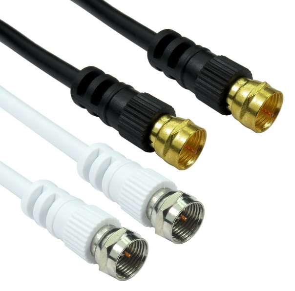
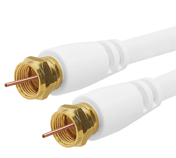
The F-Type is one of the most utilized coaxial connectors, highly common in both home entertainment and cable television systems. It is primarily used to connect antennas, cable modems, set-top boxes, and satellite receivers to coaxial cables. The most notable feature of the F-Type connector is its basic screw-on design; it assures reliability and security for the connection without requiring more tools or complicated installation procedures. It is designed to use with 75-ohm impedance cables, which are standard for most consumer TV and satellite systems. The ability of the connector to support frequencies up to 1 GHz makes it ideal for cable television, digital TV, satellite systems, and broadband internet connections that demand clear signals for good reception.
In terms of power handling, the F-Type connector normally can handle up to 20 watts. This is adequate for the majority of residential cable systems, which have moderate signal strength and a relatively short distance of transmission. In a standard setup for cable television, for instance, the F-Type connector is used to connect the coaxial cable from the wall outlet to the television receiver; the power levels in such situations usually remain within this range. However, in systems that need higher power, say in broadcast or satellite applications, other connectors may be used, such as the N-Type. Although the power rating of an F-Type connector is low compared to other RF connectors, its cheapness and ease of usage make it very suitable for residential cable systems where the power handling is not an issue.
The frequency range of the F-Type connector is usually up to 1 GHz, which is perfect for most TV and satellite systems. This makes it suitable for systems operating in the UHF and VHF bands, where many standard television broadcasts are transmitted. Application Frequency This, however, is normally inadequate in areas such as higher-frequency applications: for example, radar and satellite communications, which demand very high frequency-rated connectors, such as the SMA and N-Type. The F-Type connector, on the other hand, has its usual field of application in house installations to economically and effectively connect either cable or satellite systems to a TV set. The typical VSWR for an F-Type connector is 1.2:1, which is indicative of good signal transfer with minimal reflection, hence the connection will maintain optimum performance without significant loss of signal.
TNC (Threaded Neill-Concelman) Connector
The TNC connector is one version of the BNC connector designed to provide improved performance at higher frequencies. The TNCs are usually applied when an application requires durability, a high-frequency response, and a secure connection. The only difference between the TNC and BNC connectors is the type of coupling. While the BNC connector has a bayonet-style locking mechanism, the TNC connector features a threaded coupling that provides for even better security of connection in cases of vibrations or other types of mechanical stress. This design makes the TNC connector ideal for use in applications such as wireless communications, GPS, and radar systems. The TNC connector is most commonly used with 50-ohm impedance coaxial cables, and by design, it can handle frequencies right up to 11 GHz, giving it a considerable advantage over BNC connectors rated up to 4 GHz.
In terms of the power handling, the typical rating for the TNC connector is up to 100 watts at lower frequencies, with the rating falling as the frequency rises. This might shrink down to as low as about 50 W, especially with the frequency rising, like to 5 GHz or higher to 10 GHz. That, however, will be highly dependent on the design and type of materials used. All these reasons make the TNC connector apply well to moderate power applications like in radio communication systems, since generally the power levels stand within this range. By comparison, N-Type connectors, also used in high-power systems, can support power levels up to 1,000 watts, making them a better choice for very high-power applications. However, for most RF communication systems, the power handling and frequency response of the TNC connector are sufficient to ensure reliable performance.
Voltage Standing Wave Ratio is usually about 1.2:1 or less in standard TNC connectors. In addition, signal reflection will not be detected, which enhances the level of signal transmission. VSWR should be something that must not be omitted in high-frequency RF as it affects signal integrity where data sometimes gets lost and damaged. It features a low VSWR-a consequence of which TNC connector devices can transmit clear, interference-free signals with the least amount of noise, making it highly applicable for communication systems such as radar, GPS, and wireless. For example, in the case of a radar system, keeping VSWR small means a clearly transmitted and uncorrupted signal will be much more reliable when it comes to detection and the measurement of target distance. Low VSWR in wireless communications minimizes the loss and interference that would affect the clarity of a signal, thus allowing data to be transmitted with minimal degradation.
MCX Connector (Micro Coaxial)
The MCX connector is a small form factor, high-performance RF connector that meets the demands for miniaturization in the design of mobile devices, GPS systems, and portable wireless communication equipment. The MCX has a diameter of approximately 6 mm, thus making it of very small size. That is why this connector has been extensively used in many applications where other types, such as SMA or BNC, cannot fit. The connector operates within a typical frequency range from 0 to 6 GHz, enveloping wide fields of communications, including GPS, Bluetooth, and Wi-Fi, among other short-range wireless technologies. It is within this frequency that the MCX connector performs admirably for the transmission of a signal in those systems that do call for high-frequency applications, within a small factor. In mobile devices, for instance, the MCX connector can be connected to antennas for coupling with the radio system of the device, thus enabling high-quality communication in small, space-effective packages.
The power handling capability of the MCX connector is normally lower compared to larger connectors, such as N-Type and SMA connectors, with a typical power rating of about 10 watts at the lower frequency. However, most low- to moderate-power applications, such as consumer electronics or handheld communication devices, operate within a range of 1 to 5 watts of signal power, which the MCX connector is more than sufficient for. A good example is a portable GPS receiver, where the power involved in its operation is generally very low, and the MCX connector can easily transmit these signals with no degradation of quality. At very high-power application systems, such as in broadcasting or radar systems, respectively, an N-Type connector-a unit capable of handling power to a level of 1,000 watts-may be better used due to its larger handling capacity. Although less power-rated, the small build-up and effective signal transferring justify the MCX as perfectly useful when it comes to size and/or power efficiency.
The impedance of the MCX connector is usually 50 ohms, which is the usual for most RF communication systems; thus, it can easily be connected with a wide range of coaxial cables, such as RG-174 and RG-316 cables, which are normally used for short-distance communication systems. Besides, the MCX connector presents a low VSWR of typically 1.2:1 or lower to ensure a minimum signal reflection and an optimal transmission efficiency. A low VSWR is critical in ensuring that the signals transmitted through an MCX connector are clear and free of interference, thus making it perfect for wireless communication systems that need high fidelity. For instance, in wireless data transmission, keeping a low VSWR will prevent loss of signal and assure that the data reaches its destination without degradation or loss.
UHF Connector (PL-259)
The UHF connector (PL-259) is a popular RF connector commonly used in amateur radio, CB (citizens band) radio, and various communication systems. It is widely known for its robustness, affordability, and ability to handle moderate power levels. The PL-259 connector is typically used with 50-ohm impedance coaxial cables, such as RG-8, RG-58, and RG-213, which are standard in radio communication systems. The connector itself is usually made of brass or nickel-plated brass for durability and resistance to corrosion, especially in outdoor installations like antennas for ham radio or base stations. Among the main merits of the PL-259 connector is that it can deliver reliable performance at frequencies up to 300 MHz, covering the greatest part of amateur radio bands and short-range communications.
In terms of power handling, the UHF connector can generally support 50 watts of continuous power in the lower frequencies. Thus, it is suited for applications in low and medium power communication systems where efficiency and strength are highly desired but without the concern of extremely high power levels. As such, in an amateur radio setup, a transmitter with a power output of 10-20 watts would commonly use the PL-259 connector to connect the radio to the antenna system for strong signal transmission. However, for higher power systems such as broadcast radio or professional communications, connectors like the N-Type are more appropriate, which can handle up to 1,000 watts. The PL-259 is inadequate for very high-power applications, but the power handling will suffice for most home radio installations, allowing operators to communicate effectively with the least signal loss or degradation.
The VSWR or Voltage Standing Wave Ratio for the UHF connector ranges from 1.3 to 1.5:1, somewhat above that compared to other RF connectors such as the N-Type. However, there is decent signal efficiency provided when used at a more conventional VSWR of greater than one. When used with such a VSWR, more signal reflection may occur, which leads to the wasting of power and creates potential signal interference. For instance, at an amateur radio station, a VSWR of 1.5:1 would mean that only a very small portion of the transmitted signal is reflected back to the transmitter; it is nonetheless within very acceptable limits for reliable communications. In high-reliability applications where signal integrity is paramount, such as in radio systems operating at very high frequency or professionally, a lower VSWR would be acceptable-usually in the range of 1.1:1 to 1.2:1-and thus could be replaced by SMA or N-Type connectors.

