Table of Contents
Coaxial Cable
Coaxial cable is a type of transmission line that is used to carry high-frequency electrical signals with low losses. It is composed of a central conductor, an insulating layer, a metallic shield, and an outer insulating layer. The shield and the central conductor are on the same axis; thus, the name “coaxial.” Overall, the cable is designed to keep the signal being transmitted intact.
Characteristics and Construction: The coaxial cables are designed to keep the signal being transmitted whole. The central conductor is typically made of excellent conducting material, such as copper or aluminum. The insulating layer is typically made of polyethylene or Teflon. It is used to prevent any signal from leaking and makes sure that the signal is only in the central conductor. The outer insulating layer and the metallic shield keep the cable physically intact and prevent outside interference . The signal is also sent back to the sender using the metallic shield.
Common Types: The most common coaxial cables include:
RG-6: this is the most common type of coaxial cable used in residential and commercial buildings to supply cable television and the internet . It is used because it has a large conductor and a thick insulating layer, making it better at transmitting signals over long distances.
RG-59: this type is also widely used, especially in closed-circuit television, CCTV, and security camera installations. It is designed using a smaller and flexible cord, making it better for small spaces.
RG-11: this type of coaxial cable is mostly used for transmitting CATV and HDTV signals over long distances. It transfers the signal over these long distances due to its large size and a thick insulating layer.
Performance: The performance of the coaxial cables is measured in terms of the signal lost in transmission and the impedance. For example, at 50 MHz, the RG-6 cable loses about 6.4 dB of the signal per 100 meters, while the RG-59 loses about 11.4 dB/100m. A standard coaxial cable with a resistance of 75 ohms will provide a reliable PBTV system since most radio and TV receivers have the storage impedance.
Advantages: The highlighted features make the coaxial cables to be selectively use in the modern world. The major advantages of the coaxial cables on other transmission lines are:
-
minimal signal attenuation during transmission
-
the cables can be easily installed and are flexible.
-
The cables are relatively cheap.
Limitations: However, the cables have the following drawbacks
-
signals over long distant will tend to lose their quality
-
costly.
Waveguide
Introduction: Definition, and uses.
Waveguides are waveguide they are devices that conduct Electromagnetic wave from one point to another. They are particularly useful in the microwave and millimeter wave frequencies, where they offer advantages based on power attenuation and efficiency.
-
Basic principles and design.
The waveguide is a hollow metallic conductor, and it is often deployed with cross sections that appear rectangular, or circular. It works by confining the electromagnetic wave to a specific path, so they travel with minimum loss . The operating frequencies and the dimensions of the waveguide are very critical. For instance if the dimension of the standard WR-90 rectangular waveguide is 2.286 cm by 1.016 cm, then the waveguide will be able to support frequencies between 8.2 GHz to 12.4 GHz.
3 Advantages and Limitations.
Waveguides offer the following advantages below:
-
Low loss: it has a lower loss at the high frequencies, compared with the coaxial cables, cable which is conducting the same function. Thus it will be a waste to deploy ordinary cables to support such high frequencies.
-
High power handling: it can handle higher power without any notice of signal degradation, and the later is very important for radar and satellite communications.
Waveguides also have the following disadvantages:
-
size and weight: waveguides are not only heavy, they are also large compared with the coxial cable this constitutes a disadvantage on their part.
-
Flexibility: the waveguide is regarded as rigid transmission lines, as such it is very difficult to bend.
-
Applications
-
In radar systems; the waveguide is deployed to transport microwave signal of high power from the radar transmitter up to the antennas.
-
In satellite communications system; for example, the waveguide connection, a link between satellite antenna, transceivers etc. For example, the waveguide is used in the transport of radio frequency signal of high frequency between two point. .
Microstrip Line
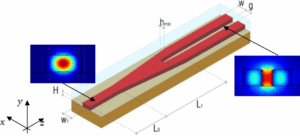
Microstrip lines are transmission lines designed to transfer signals at microwave frequency. They contain a conducting strip separated by a dielectric substrate from the ground plane. The use of these lines in microwave circuits is common owing to the compactness and simplicity of their implementation. This paper is focused on the applications of microstrip lines, their properties, and advantages.
Structure and Performance
A microstrip line consists of a metal strip that acts as a conductor situated above the substrate and one or more ground planes at the bottom. The strip width, height of the substrate, and the dielectric constant of the substrate determine the characteristic impedance of the line . For example, a microstrip line with a substrate dielectric constant equal to 4.0, substrate height equal to 1.6 mm, and strip width equal to 3 mm usually has an impedance feature equal to around 50 ohms.
Integration with Antenna Elements
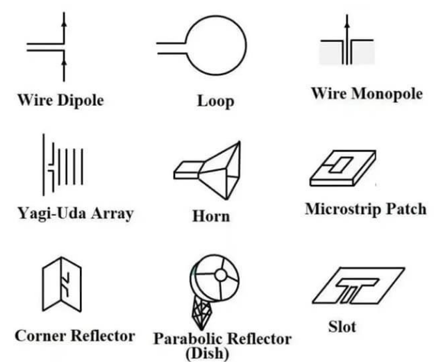
One of the most popular applications of microstrip lines refers to various printed antennas, such as a patch. Such approach is conditioned by the fact that there are ways to manufacture both microstrip lines and antennas on a single substrate simply . For example, a microstrip patch, which is designed to operate at a frequency equal to 2.4 GHz, may be fed using a microstrip gap line, which feeds signals with much efficiency at the desired frequency in any wireless communication systems.
Advantages
The main advantages of microstrip lines compared to other types of transmission lines are the following:
compactness – this property is related to the planar design of microstrip lines, making them lighter and more convenient compared to other ways of signal transferring;
ease of fabrication – the implementation of microstrip lines requires no specific facilities and can be widely made by using existing printed-circuit board technologies;
capability of integration – a variety of other circuit elements and devices can be implemented on the same substrate. The main limitations of the considered transmission lines refer to the following unique features:
losses – the latter may be related to microstrips for two reasons: the dielectric loss in the substrate material and the skin effect in the used conductor. The latter may cause degradation in the signal line at higher frequencies;
dispersion – a dependence between the phase velocity of a signal and the wave frequency. The more presence of this effect, the higher is the risk for the band-limited signals to become distorted. The applications of microstrip lines can be numerous and mainly include the following ones:
MICs: the latter may use microstrip lines for input and output matching, impedance transforming, and routing the signal to the proper output;
one of the main applications of these lines is to feed the RF signal presented to the input of the information system to the antenna. The band-limited properties of these applications allow both wideband and single-frequency applications;
filters and couplers may also be implemented. Their convenience is determined by the universality and simplicity of their fabrication properties.
 Balanced Line
Balanced lines are a type of transmission line intended to convey electrical signals with minimal noise and interference, unlike the unbalanced coordinate lines. The balanced lines have equal and opposite signals carried by the two conductors, and they inherit the noise rejection from this measure. The prime function of the transmission difference lines is the capacity to operate in the presence of external electromagnetic interference . There are two primary types of balanced lines:
-
Twisted pair – this consists of two insulated conductors that are twisted together to arrive at greater cancellation of any noise on the lines that might be generated externally. The category includes the Cat 5e with a bandwidth of 100 MHz used with Ethernet networks .
-
Shielded twisted pair (STP) – similar to twisted pair, but as the name suggests, it comes with a shielding layer, ensuring greater extent of EMI protection. The Cat 6a STP can operate at frequencies up to 500 MHz, suitable for high-speed data uses.
Baluns and Impedance Matching: a balun is a type of device that takes the unbalanced signal and converts it into a balanced one (thus the term “balanced-to-unbalanced” transformer). As such, a balun is used wherever a balanced device interfaces with an unbalanced system . For example, the balun may be used to attach a microphone with a balanced line to an audio mixer that operates the best with unbalanced line inputs. Likewise, in order to prevent the mismatch in impedance, meaning to maximize the power transfer to each part of the system and reduction of the condition called “reflections”, the impedance of the two parts attached should match perfectly . In the ratio 1:1, a 200-ohm balanced antenna can be connected to a 200-ohm unbalanced feed line with a 1:1 balun device.
Advantages: balanced lines have a number of distinct advantages over the unbalanced lines:
-
Rejection of noise – the prime advantage of these lines is the much superior noise rejection property which makes them suitable for audio and data transmission in relatively noisy environments.
-
Reduction of crosstalk – this has to do with the proximity of one line with another when multiple pair cables are used. The more physically separated the two conductors are and the greater twist there is, the lesser crosstalk is produced. The prime disadvantage of the balanced cables, compared to the unbalanced ones, is the additional cost associated with the addition of the shielding, where used. As the name suggests, the 20 Ohm coaxial cables and other types of unbalanced lines are also unshielded which makes them inherently cheaper as there are no additional external mechanisms to mitigate EMI.

