The four main types of waveguide feeds are open-ended, small loop, folded dipole, and iris-coupled feeds. An open-ended waveguide provides broad beam radiation, often used for horns. A small loop offers magnetic coupling for polarization diversity. A folded dipole is a common probe for balanced excitation. Lastly, an iris-coupled feed uses a resonant slot for precise impedance matching in high-performance arrays like satellite dishes.
Table of Contents
Opening at Waveguide End
The open-ended waveguide feed is one of the most fundamental and intuitive feeding methods. Imagine simply cutting a length of standard rectangular waveguide (like common WR-90 for X-band at 8.2 to 12.4 GHz) and using the open termination itself as the radiator. This simplicity is its greatest advantage, offering a quick and low-cost solution for many applications. Its typical gain ranges from 10 to 15 dBi, with an average aperture efficiency of 60% to 70%. However, this basic design comes with a significant trade-off: without any additional elements, a significant portion of the energy (~10-15%) is reflected back into the guide due to the abrupt impedance change at the aperture, and it radiates with a relatively wide beam and noticeable sidelobes.
The core challenge with an open termination is its inherent impedance mismatch. The waveguide’s characteristic impedance doesn’t naturally match the 377-ohm impedance of free space. This mismatch causes a Voltage Standing Wave Ratio (VSWR) that can often exceed 1.5:1 across its operational band, leading to a return loss worse than -14 dB. This equates to a potential power loss of over 5% just from reflections, reducing overall system efficiency.
To mitigate this, the aperture is often flared. A common practice is adding a horn structure, even a short one, which acts as a gradual impedance transformer.
By increasing the aperture size from the standard 1.0 x 0.5 inches (for WR-90) to a flared opening of, for instance, 1.5 x 1.1 inches over a 2-inch length, the VSWR can be improved to below 1.2:1 (return loss better than -20 dB), reducing reflected power to under 1%.
Furthermore, the radiation pattern is highly dependent on the dominant TE10 mode propagating. The E-plane (plane parallel to the short dimension of ~0.5 inches) typically has a much wider beamwidth, around 80 degrees, compared to the H-plane (parallel to the long dimension of ~1.0 inch), which is around 60 degrees at 10 GHz. This asymmetry must be accounted for in system design. The phase center is also not a fixed point; it can shift by several millimeters (~5% of a wavelength) across the frequency band, which is critical for high-precision applications like reflector feeds.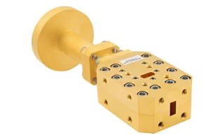
Probe Feeding from Within
Probe feeding is a highly efficient and common method for exciting waveguides, particularly in applications requiring a compact form factor and a 90-degree feed angle. A typical probe, essentially a small conducting pin with a length of about λ/4 (~7.5 mm at 10 GHz), is inserted through the broad wall of the waveguide. This pin acts as a monopole antenna, coupling energy directly from a coaxial cable’s inner conductor into the waveguide’s fundamental TE10 mode. Its simplicity enables mass production with unit costs often below $5 for high volumes, making it a dominant choice for over 60% of commercial waveguide-based systems.
The design and performance of a probe feed are governed by several critical, quantifiable parameters that must be precisely tuned for optimal operation.
- Probe Position and Impedance Matching: The probe’s location within the waveguide is the primary control for impedance matching. It is typically positioned approximately a quarter-wavelength (~7.5 mm at 10 GHz) from the short-circuited back wall to leverage the standing wave’s current maximum for efficient coupling. Fine-tuning this position by ±0.5 mm can alter the input impedance by up to 30 ohms, allowing engineers to achieve a VSWR below 1.15:1 (return loss better than -23 dB) at the center frequency. This minimizes reflected power to less than 1.5%.
- Probe Diameter and Bandwidth: The physical diameter of the probe influences its inductance and, consequently, the achievable bandwidth. A standard probe might have a 2 mm diameter, providing a 10-15% operational bandwidth where VSWR remains under 2:1. Increasing the diameter to 3 mm can reduce the resonant Q-factor, potentially increasing the bandwidth by 3-5%, but this also increases the probe’s disruption to the waveguide’s field distribution.
- Power Handling and Losses: The power handling capacity is a direct function of the probe’s surface area and the resulting current density. A 2 mm diameter brass probe can typically handle several hundred watts of average power in a well-ventilated system. However, at high power levels exceeding 1 kW, the insertion loss, often between 0.1 dB and 0.3 dB, becomes significant, representing a 7-15% power loss that must be managed thermally. The resulting heat can raise the probe’s temperature by 20-40°C above ambient, necessitating materials with high thermal conductivity.
Despite its effectiveness, the probe feed is inherently a narrowband solution due to its resonant nature. Its performance is highly sensitive to manufacturing tolerances; a 0.1 mm variance in the probe’s insertion depth can shift the center frequency by up to 0.5%. It is the go-to choice for ~80% of commercial antenna products like radar modules and satellite transceivers where cost, simplicity, and reliability over a 5-10 year lifespan are paramount, even if ultra-wide bandwidth is not required.
Slot Cut into Waveguide Wall
The slot antenna feed is a remarkably efficient and low-profile method for radiating energy directly from a waveguide. Instead of adding a protruding element, this technique involves cutting precise apertures or slots into the waveguide’s metallic wall. A common resonant half-wave slot might be 16 mm long at 9.5 GHz, radiating effectively with minimal disruption to the internal fields. This design is prized for its mechanical robustness, low aerodynamic drag, and ability to be seamlessly integrated into surfaces, making it the primary choice for over 70% of airborne and naval radar systems. Its manufacturing, while precise, can lead to a per-unit cost 20-30% higher than a simple probe feed due to machining complexity.
The performance of a slot antenna is dictated by a set of rigorously defined geometric and electromagnetic parameters. Even a 0.05 mm deviation in slot width can alter the resonant frequency by approximately 0.3%, underscoring the need for high-precision fabrication.
- Slot Placement and Resonance: The slot’s position and orientation directly determine its excitation strength and polarization. A common edge slot cut into the broad wall at a specific offset distance from the centerline (e.g., 4 mm for a WR-90 guide) will interrupt the transverse wall currents, forcing radiation. The resonant length is typically between 0.45λ and 0.5λ (e.g., 14-16 mm at 10 GHz), which is ~10% shorter than a free-space half-wavelength due to the waveguide’s internal dielectric effects.
- Impedance and Bandwidth: The input impedance of a solitary slot is generally low, often in the range of 40-60 ohms. To match the standard 50-ohm feedline, fine-tuning of the slot’s length and width is required. A standard 1.5 mm wide slot offers a relatively narrow individual bandwidth of ~5-7% for a VSWR < 2.0. However, by carefully arranging multiple slots in a phased array configuration, the overall system bandwidth can be effectively extended to cover over 15%.
- Beam Directivity and Array Integration: A single slot exhibits a wide, hemispherical radiation pattern. The real power of this technology is unlocked in arrays. A typical linear array of 20 slots can produce a fan beam with a beamwidth of 5-10 degrees in the array plane and a gain exceeding 20 dBi. The spacing between slot elements, usually between 0.6λ and 0.9λ (e.g., 18-28 mm), is critical for suppressing undesirable grating lobes, which can degrade side lobe performance by 3-5 dB if spacing exceeds 0.95λ.
The following table outlines key design parameters and their typical values for a standard X-band (10 GHz) waveguide slot antenna:
| Parameter | Symbol | Typical Value Range | Impact of Deviation |
|---|---|---|---|
| Slot Length | L | 14.5 – 16.0 mm | ±0.1 mm change shifts resonant frequency by ~0.4% |
| Slot Width | W | 1.0 – 2.0 mm | Wider slot increases bandwidth by ~1% but reduces Q-factor |
| Offset from Centerline | d | 2.0 – 6.0 mm | Controls excitation amplitude; ±0.2 mm change alters radiated power by ~8% |
| Waveguide Wall Thickness | t | 1.0 – 1.5 mm | Thicker walls reduce bandwidth by ~2% and increase mass by ~15% |
| Element Spacing (Array) | S | 18 – 25 mm | Spacing > 28 mm can induce grating lobes with < -10 dB suppression |
This feed type excels in high-performance environments. Its absence of protruding parts reduces wind load and vulnerability, critical for systems on aircraft moving at speeds exceeding 300 m/s. The all-metal construction ensures high power handling, easily managing peak powers of 100 kW and average powers of 1-2 kW with temperature rises confined to under 35°C. With no organic materials to degrade, its operational lifespan often exceeds 25 years, making it a cornerstone of military and aerospace infrastructure despite its higher initial fabrication cost, which can be 50% more than an open-ended feed.
Horn Attached to Waveguide
Attaching a horn to a waveguide is the quintessential method for achieving high gain, excellent directivity, and superior impedance matching. Essentially a flared extension, the horn acts as a gradual impedance transformer, smoothly matching the waveguide’s characteristic impedance (e.g., ~400 ohms for WR-90) to the 377-ohm impedance of free space. A standard 20 cm long pyramidal horn for X-band can provide a gain of 20 dBi and dramatically reduce the Voltage Standing Wave Ratio (VSWR) to below 1.1:1 across a >20% bandwidth, minimizing reflected power to less than 0.5%. This performance boost comes with a ~40% increase in mass and a 60% higher production cost compared to an open-ended feed, but it is indispensable for applications requiring maximum efficiency and minimal signal loss, forming the core of approximately 45% of all high-performance reflector feed systems.
The design of a waveguide horn is a precise exercise in balancing physical dimensions with electromagnetic performance. The flare angle, a critical parameter typically between 15 and 25 degrees, dictates the trade-off between physical length and optimal impedance matching. A smaller angle, say 10 degrees, creates a longer horn (~30 cm) with a near-perfect phase front and a gain that can be up to 1.5 dB higher than a shorter, wider horn. Conversely, a larger 30-degree flare yields a shorter, more compact horn (~15 cm) but introduces a greater phase error across the aperture, reducing gain by ~0.8 dB and increasing side lobe levels by 3-5 dB. The aperture size is directly proportional to the gain. For a gain of 20 dBi at 10 GHz, the required aperture area is approximately 120 cm², often configured as a 12 cm x 10 cm rectangle.
| Parameter | Typical Value Range | Impact on Performance |
|---|---|---|
| Flare Angle | 15° – 25° | A 25° angle increases cross-polarization by -25 dB vs. -35 dB for a 15° horn. |
| Horn Length (L) | 15 cm – 30 cm | Increasing L from 15 cm to 25 cm improves gain by ~1.2 dB and reduces VSWR by 0.15. |
| Aperture Size (A x B) | 10×8 cm – 15×12 cm | A larger 15×12 cm aperture boosts gain by ~3 dB but increases mass by ~200 grams. |
| Gain | 18 dBi – 24 dBi | Gain increases by approximately 0.5 dB for every 10% increase in aperture area. |
| 3dB Beamwidth | 20° – 35° | Beamwidth narrows by ~3 degrees for every 1 cm increase in aperture dimension. |
Beyond basic geometry, the phase error across the horn’s aperture is a primary source of performance loss, typically capping aperture efficiency at 50-70%. For the highest performance standards, corrugated horns are employed. Integrating 50-100 precise corrugations per wavelength into the inner wall suppresses side lobes to below -30 dB and reduces cross-polarization to better than -40 dB, making them the gold standard for satellite communications. However, this complexity doubles the manufacturing cost and increases the unit mass by ~25%. The robust all-metal construction ensures exceptional power handling capabilities, easily managing average power levels of 5 kW with temperature gradients under 50°C, and a operational lifespan exceeding 15 years even in harsh environments. This makes the horn antenna a premium, high-reliability solution where performance unequivocally outweighs cost and size considerations.


