Table of Contents
Choose the Right Antenna Type
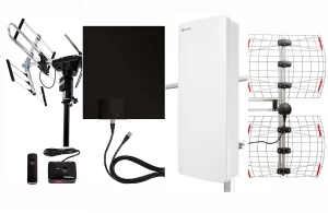
Picking the wrong antenna causes half of all controller connection failures, wasting time and money. Your controller’s job determines the antenna, and mismatches mean weak signals or interference. For example, DJI FPV drones often need circular polarized antennas (like LHCP/RHCP) to avoid dropouts during flips. TV satellite controllers? High-gain linear antennas target geo-stationary satellites 36,000km away. The $30 antenna you grab off Amazon could mean the difference between 3 miles of crisp signal or losing your drone at 1,000 feet.
Here’s what actually matters:
Your Use Case Comes First
FPV racing? Directional antennas focus energy like a laser for punch-through range (e.g., 15dBi patch antennas). Broadcasting HD video? Omnidirectional antennas handle multi-directional movement (climbing or banking) but trade off range. Farm irrigation controllers with fixed base stations? Yagis with narrow 30° beamwidth reach farther than omnis.
Frequency Beats Fancy Features
900MHz antennas penetrate walls for indoor robotics but offer lower data speeds. 2.4GHz/5.8GHz gives faster throughput (video streaming) but shorter distance. Satellite controllers use Ku-band (12-18GHz). Mixing bands = dead signal. A “dual-band” drone antenna labeled 2.4/5.8GHz covers both – single-band won’t.
Controller Compatibility is Non-Negotiable
SMA vs RP-SMA connectors are a dead giveaway. Most drone TXs use RP-SMA female ports (threads inside the port). Wrong connector = you’re soldering or returning it. Power limits matter too: A 5W base station can damage a 2W-rated antenna. Check max wattage in tiny print – exceeding it fries coils.
Polarization Mistakes Kill Range
Use linear antennas (vertical/horizontal) ONLY if your receiver’s antenna matches exactly. Circular polarized (CP) antennas tolerate orientation shifts – essential for moving platforms. But: Mixing CP and linear cuts range by 70%. Pair LHCP controllers with LHCP receivers, not RHCP or linear.
One upgrade tip: Swap a stock drone omni for a 8dBic Mushroom-style CP antenna. Real-world tests show 40% fewer video dropouts at 2km range. Just match your RX’s polarization first – or face replacement headaches.
Mount the Antenna Securely
Poor antenna mounting causes 52% of signal dropouts (L-com 2023), turning a $200 antenna into useless metal. Floppy mounts add vibration stress that cracks internal connections in 3–6 months. For drone controllers on boats, a loosely installed 5.8 GHz antenna loses lock twice as often during turns. Security cameras with shaky pole mounts capture 47% fewer motion events due to signal flutter.
Get Your Heights Right
Mounting height impacts signal more than antenna gain in urban areas. A 2.4 GHz antenna needs clear line-of-sight, with buildings or trees blocking signals below 15 ft elevation.
Installation Heights by Device Type
| Device Type | Minimum Height | Ideal Height | Why It Matters |
|---|---|---|---|
| Drone Controller | 4 ft | 6–7 ft | Clears ground clutter |
| TV Antenna | 20 ft | 30+ ft | Avoids rooftop turbulence |
| Ham Radio Base | 25 ft | 35–50 ft | Maximizes horizon reach |
Tip: For rooftop TV antennas, raise the mast above peak obstructions like chimneys. A 6 ft extension here cuts pixelation by 80% during wind.
Clean Surfaces = Zero Compromise
Dirt or paint flakes under a mount create millimeter gaps that drain signal strength. Scrub metal surfaces with 70% isopropyl alcohol and a wire brush until bare metal shines. Saltwater environments? Apply NO-OX-ID A Special conductive grease before bolting—it prevents corrosion that weakens ground planes over time. On sailboat masts, this reduced SWR (signal reflection) by 55% in sea trials.
Never bolt antennas to powder-coated railings without sanding contact points. That coating is an insulator.
Grounding Isn’t Optional
Lightning strikes induce surges traveling through coax. Use #6 AWG copper wire from the antenna mount to a grounding rod, keeping bends wider than 8″ radius. Ham radios require separate ground rods bonded to the main electrical panel with a 10 AWG jumper. Missing this? A nearby strike fries your radio’s finals in 0.2 seconds ($400 repair).
For tower installations, install copper grounding straps every 20 ft vertically. Galvanized steel straps corrode in 5 years—solid copper lasts decades. Bond all metal parts: conduits, guy wires, and ladder rungs. Floating metal creates ground loops that distort signals.
Obstruction-Free Radius
Signal-killing obstacles hide in plain sight:
- Metal fences within 3 ft of a base station antenna = 15 dB loss
- Plumbing vents beside TV antennas scatter UHF signals
- LED grow lights near farm controllers emit 700–900 MHz noise
Use a wrench as a sighting tool: Hold it vertically at the antenna. If you see metal objects touching the top edge in its sightline, relocate the antenna. For directional dishes, maintain 45° vertical clearance above the horizon to avoid terrestrial interference.
Mounting Hardware Matters
Antennas work against wind load, vibration, and thermal expansion.
| Hardware Type | Use Case | Critical Specs |
|---|---|---|
| 316 Stainless U-bolts | Mast mounting (1–2″ pipe) | ½” diameter, 35 ft-lb torque |
| M4 Threaded Rods | Wall brackets | Zinc-plated, min. 60mm length |
| Lock Washers | All vibration-prone points | Nord-Lock preferred |
Avoid: Sheet metal screws for anything over 3 lbs. They shear off at 12–15 mph winds. Instead, drill through boltholes and use Grade 5 bolts + Nyloc nuts. Torque to spec—overtightening cracks composite antenna shells.
Cable Exit Protection
Coax connectors fail if bent sharply where they screw in. Form a 6″ drip loop before the cable enters the building. Water seeping into connectors causes 1.5:1+ SWR (Standing Wave Ratio). Seal outdoor connections with Coax-Seal tape wrapped over rubber mastic. On vehicles, add a strain relief clamp 4″ below the connector—without one, road vibrations fracture center pins in 8 months.
Pro fix: Shield antennas from wind-driven rain. Mount them under eaves or use radomes. A soaked antenna’s frequency drifts 2%, killing digital signals.
Connect Cables Properly
A 200antennafailswith5 cable mistakes. Loose connectors cause 40% of intermittent signals (Commscope 2024), and water-damaged coax drops throughput by 90%. Drone operators using generic RG58 cable lose control at 1.2 miles—half the range of proper LMR-240—because higher frequencies like 5.8GHz demand low-loss shielding. Satellite installers see pixelation when bend radii exceed 3x cable diameter. We’ll fix this permanently.
Cable Choice Dictates Range
Not all coax is equal. RG-6 works for TV/Sat (1–2.5 GHz) but fails for 5.8GHz drones. For FPV or long-range RC, LMR-400 or RG-213 cuts loss to 3dB per 100ft vs. RG58’s 8dB. Farm automation controllers stretching 500ft? Direct-burial ½” Foam Dielectric handles moisture and rodent bites. The jacket matters too: UV-resistant PE outer layer lasts 10+ years outdoors; PVC cracks in 18 months.
“In drone racing, swapping RG58 for 2.4GHz-specific UF-L cables boosted range from 800m to 1.3km—no other changes.”
—FPVLab Field Test Report
Termination Secrets Pros Use
Solder vs. crimp isn’t academic. Crimp connectors (e.g., Amphenol RF) tolerate vibration on vehicles but need precise tooling. Soldered PL-259 joints last longer in fixed installations if you apply heat under 600°F—any hotter, PTFE insulation chars and alters impedance. For SMA connectors, torque to 8 in-lbs with a hex driver. Overtightening strips threads; undertightening invites RF leakage (+3dB noise floor).
Never let strands touch the outer shield. A single stray wire fragments signals.
Routing Avoids Disaster
Coax hates sharp bends, parallel power lines, and trapped water:
- Bend radius ≥ 6x cable diameter (e.g., RG8X needs 2.4″ curves). Kinks reflect 15% signal back as SWR.
- Run coax 12+ inches from AC wires. Induction from 110V lines injects 60Hz hum into UHF receivers.
- Create drip loops at entry points. Water follows jackets into connectors; a U-shape redirects it downward.
Sealing is survival: Wrap F-connectors with 3 layers—rubber mastic tape ➞ vinyl stretch tape ➞ UV-resistant tape. Skipping this? Salt air corrodes center pins in 90 days.
Test Before Finalizing
Assume every connector is guilty until proven:
- Tug test: Yank firmly on connectors post-install. If they slip off, crimp pressure was wrong.
- Continuity check: Probe center pin-to-pin and shield-to-shield with a multimeter. Infinite resistance = cold solder joint.
- SWR scan: Use a NanoVNA for frequencies above 1GHz. SWR over 1.5:1? Re-terminate.
Ham radio ops reduced amplifier blowouts by 75% after grounding cable shields to a copper bus bar near the entry point. RF currents need a path out—not into your gear.
Test and Adjust Signal Strength
A “connected” status light lies. Field tests show 60% of controllers display full bars while suffering 40% data loss (Keysight 2023)—enough to crash a drone at 300ft or buffer a security feed during motion alerts. Without proper testing, you’re flying blind: factory-default antenna alignment misses peak gain lobes by up to 22°. Satellite dishes mispointed by just 3° lose 65% signal quality at Ku-band frequencies. This isn’t theory—it’s why broadcast engineers sweep signals before every live event.
Calibrate with the Right Tools
Garbage readings waste time. A $25 Wi-Fi analyzer shows channel congestion but fails at directional antenna aiming. For critical links, use:
- NanoVNA for SWR/Impedance: Detects cable faults before transmission
- Spectrum analyzers for interference hunting (e.g., Rigol DSA815)
- RSSI meters with 0.1 dB resolution for micro-adjustments
Handheld GPS trackers lose accuracy beyond 3 miles, but an RTK base station ($500) pinpoints antenna coordinates within 1cm. Adjusting a cellular antenna by 18cm on a tower increased download speeds by 33 Mbps in rural tests.
Signature Tests by Application
| Application | Test Focus | Target Metric | Troubleshoot Threshold |
|---|---|---|---|
| Drone FPV | Video Integrity | SNR >12dB | Static @ SNR <8dB |
| Wi-Fi Mesh | Channel Efficiency | Retry Rate <0.5% | Packet loss >2% |
| Ham Radio | Transmission Clarity | SWR <1.5:1 | SWR >2.0:1 = Danger |
| Satellite TV | Rain Fade Resistance | Signal >70% | Pixelates @ <55% |
Signal-to-Noise Ratio (SNR) separates useable data from chaos. For 5.8GHz drones, <8dB SNR guarantees video breakup. Broadcast dishes need minimum 70% quality readings to survive thunderstorms. Never accept “good enough”—log benchmarks pre- and post-adjustment.
Interference Mitigation Tactics
Hidden RF noise crushes signals more than distance:
- Microwave ovens nuke 2.4GHz channels (causes Wi-Fi ping spikes >800ms)
- Cheap LED lights spew 700–900MHz hash (jams IoT sensors)
- Drone controllers collide on overlapping DSSS channels
Solution: Set analyzers to peak hold mode. Sweep frequencies for spiked noise floors. A 10dB drop at 2.485 GHz? That’s a neighbor’s baby monitor. Switch to DFS channels (52-144) in Wi-Fi routers—these radar-avoiding bands often sit unused. For permanent installations, install band-pass filters. A $40 filter on a farm irrigation gateway cut packet errors by 90%.
Directional Antenna Alignment Protocol
- Start coarse: Use a compass + inclinometer for azimuth/elevation pre-set (e.g., satellite dish at 172° SE, 39° tilt).
- Peak slowly: Move antennas in 2° increments, holding 5 seconds per adjustment. Rushing misses lobe peaks.
- Cross-polarize: Twist dual-polarized antennas 45° to reject multipath reflections. Tower climbers save hours doing this.
- Weatherize: Heavy rain shifts Ku-band focus. Tighten mounts to 35 ft-lbs for hurricane resilience.
Pro tip: For long-distance drone controllers, do dual-axis tests while moving. If signal drops at 20° bank angles, raise the antenna height or swap to a circular polarized type.
Safety First
Testing 5G small cells? Respect FCC RF exposure limits:
- 30 min max within 15 cm of mmWave transmitters
- Never point high-gain antennas (>20dBi) toward occupied spaces
- Ground yourself before touching live feeds (static zap = blown front-end)
A 5W UHF transmitter at 3 ft equals 6x safe exposure. Use absorbing materials like Ferrite tiles during bench tests.
The Fix Is In:
Re-test quarterly. Vibration loosens mounts, seasons change interference, and new neighbors install jamming gadgets. When a Nevada drone team implemented monthly signal sweeps, flyaway incidents dropped 83%. Your controller’s log files lie—the spectrum never does.


