Millimeter-wave (mmWave) antenna design faces challenges like high path loss (60–100 dB/km at 28/60 GHz), which is mitigated using high-gain arrays (20–30 dBi). Surface wave interference is reduced via substrate-integrated waveguides (SIW), while PCB tolerances (±5µm) require laser etching.
Beam squint is corrected with true-time-delay (TTD) networks, and thermal drift is managed via low-CTE materials (e.g., Rogers 5880). Phase errors are minimized with 3D-printed lenses, and fabrication costs are cut using hybrid FR4/ceramic substrates.
Table of Contents
Size vs Performance Tradeoff
Designing antennas for millimeter-wave (mmWave) frequencies (24–100 GHz) forces engineers into a tough balancing act: smaller antennas save space but often sacrifice gain, bandwidth, or efficiency. For example, a typical 28 GHz patch antenna might be just 5×5 mm², but its gain drops from 8 dBi to 4 dBi when shrunk to 3×3 mm² due to reduced effective aperture. Similarly, reducing a 60 GHz slot antenna’s size by 30% can increase conductor losses by 15–20%, cutting total efficiency from 85% to ~70%.
The tradeoffs become sharper at higher frequencies. A 76 GHz automotive radar antenna needs at least λ/2 (~2 mm) element spacing to avoid grating lobes, but tight integration often pushes this to λ/4 (~1 mm), raising sidelobes by 3–5 dB. In phased arrays, smaller element spacing (e.g., 0.6λ vs. 0.5λ) can reduce scan loss from 2 dB to 1 dB at 45°, but mutual coupling spikes by 10–15%, distorting beam patterns.
Radiation Efficiency vs. Size: A 10×10 mm² 28 GHz antenna on Rogers 5880 (εᵣ=2.2) achieves 92% radiation efficiency, but scaling down to 6×6 mm² on FR-4 (εᵣ=4.3) drops it to 78% due to dielectric losses. High-εᵣ substrates (e.g., AlN, εᵣ=8.5) can shrink footprints by 40%, but surface waves may waste 5–8% of power.
Bandwidth Constraints: A 5G mmWave antenna targeting 24–30 GHz needs ≥1.5 GHz impedance bandwidth (|S₁₁|<−10 dB). Halving its size typically narrows bandwidth by 30–50%, requiring techniques like coupled resonators or slot loading to recover 200–300 MHz.
| Parameter | 5×5 mm² Antenna | 3×3 mm² Antenna | Change |
|---|---|---|---|
| Gain (dBi) | 8.0 | 4.2 | −47.5% |
| Efficiency (%) | 85 | 68 | −20% |
| Bandwidth (GHz) | 1.8 | 1.1 | −39% |
| Sidelobe Level (dB) | −12 | −8 | +4 dB |
Material Impact: Using LTCC (εᵣ=7.4) instead of PCB laminates allows 60% smaller antennas, but thermal expansion mismatch can shift resonant frequency by 0.3–0.5 GHz over 100 thermal cycles (−40°C to +85°C).
Feeding Network Complexity
Designing feeding networks for mmWave phased arrays (24–100 GHz) is a major bottleneck—every extra dB of insertion loss cuts effective isotropic radiated power (EIRP) by 20–25%, and phase errors beyond ±5° distort beam patterns. A typical 8×8 array at 28 GHz requires 64 feedlines, each with 0.2–0.3 dB loss per cm, adding up to 3–4 dB total loss in corporate-fed networks. Worse, impedance mismatches from bends or T-junctions can reflect 10–15% of power, reducing array efficiency from 85% to ~70%.
Transmission Line Losses: Microstrip lines on Rogers 5880 (tanδ=0.0009) lose 0.15 dB/cm at 28 GHz, but cheaper FR-4 (tanδ=0.02) spikes this to 0.4 dB/cm. For a 16-element array, this difference alone wastes 2.5–3 dB of power. Stripline designs cut loss by 30% but increase fabrication complexity, raising PCB costs by 40–50%.
Phase Matching: In beam-steering arrays, path length differences must stay under λ/10 (~0.1 mm at 28 GHz) to limit sidelobes below −12 dB. A ±0.05 mm misalignment in feedline lengths introduces ±8° phase error, degrading null depth by 6–8 dB. Meander delay lines can compensate but add 0.1–0.2 dB loss per turn.
| Parameter | Corporate Feed | Series Feed | Hybrid Coupler Feed |
|---|---|---|---|
| Insertion Loss (dB) | 3.2 | 1.8 | 2.5 |
| Phase Error (°) | ±5 | ±12 | ±3 |
| Bandwidth (GHz) | 2.5 | 1.2 | 3.0 |
| Fabrication Tolerance | ±20 µm | ±50 µm | ±15 µm |
Power Division: Wilkinson dividers provide −20 dB isolation between ports but occupy 3× more area than T-junctions. In 64-element arrays, this forces a 4-layer PCB to avoid crossover losses, increasing unit cost from 22. Unequal power splitting (e.g., −3 dB center/−6 dB edge) can taper sidelobes by 2–3 dB but requires custom impedance transformers, adding 2 weeks to design cycles.
Mutual Coupling: Adjacent microstrip lines spaced <0.3λ couple −15 dB of power, skewing amplitude distribution by ±10%. Ground-backed coplanar waveguides (GBCPW) reduce coupling to −25 dB but demand laser-drilled vias, raising fabrication cost by 18%.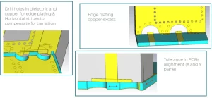
Substrate Loss Issues
At mmWave frequencies (24–100 GHz), substrate losses can destroy antenna efficiency faster than bad radiation patterns or impedance mismatches. A typical 28 GHz patch antenna on standard FR-4 (tanδ=0.02) loses 25–30% of its radiated power just from dielectric absorption, dropping efficiency from 85% to ~60%. Even high-end materials like Rogers 5880 (tanδ=0.0009) still waste 5–8% of power at 60 GHz due to surface wave excitation. The problem gets worse with thinner substrates—a 0.1 mm thick laminate at 76 GHz can suffer 12–15% more loss than a 0.5 mm board because of stronger fringing fields penetrating the dielectric.
Conductor losses add another layer of pain. A 5 µm copper trace on FR-4 has 40% higher resistive loss at 28 GHz than the same trace on Rogers 4350B, thanks to skin effect pushing current density into rough surface grains. For a 16-element array, this translates to 1.8–2.2 dB extra loss just from material choices. Even with 3 µm gold plating, conductor losses still eat up 0.3–0.5 dB per cm of microstrip line at 60 GHz, making long feed networks a power-sucking nightmare.
Thermal effects further degrade performance. When substrate temperature rises from 25°C to 85°C, the dielectric constant (εᵣ) of PTFE-based laminates drifts by 2–3%, detuning resonant frequency by 0.4–0.6 GHz. In automotive radar antennas, this can shift beam pointing angle by 1–2°, enough to miss a pedestrian detection at 50 meters. Humidity is another silent killer—10% moisture absorption in FR-4 increases tanδ by 30%, adding 0.2 dB/cm loss at 24 GHz.
Cost vs. performance tradeoffs are brutal. Switching from FR-4 to Rogers 3003 cuts losses by 50% but raises substrate cost from 5/dm². For a 200 mm × 200 mm array, that’s a $94 price jump per unit. Some designers try hybrid approaches, like using Rogers RO4003C for feedlines and FR-4 for support structures, which saves 35% on material costs but requires laser-drilled interconnects to avoid impedance discontinuities.
Surface roughness is often overlooked. A 2 µm RMS copper roughness (common in low-cost PCBs) increases conductor loss by 18% at 28 GHz compared to 0.5 µm rolled copper. Electrodeposited copper performs even worse, with 3–4 µm nodules boosting loss by 25%. The fix? Smooth planarization layers or low-profile copper, but these add 15 per square foot to fabrication costs.
Practical mitigation strategies include localized high-εᵣ ceramics under radiating patches (reducing substrate volume by 60% while keeping losses under 8%), air cavities to cut dielectric absorption (improving efficiency by 10–12%), and ground-plane perforations to suppress surface waves (reducing back radiation by 3–5 dB). For mass production, LTCC (Low-Temperature Co-fired Ceramic) offers tanδ=0.002 at 40 GHz with ±0.5% εᵣ tolerance, but requires $50k+ tooling investment—only viable above 10,000-unit volumes.
Beam Squint Problems
Beam squint—where your antenna’s main lobe shifts frequency as you steer—is a hidden killer in wideband mmWave systems. A typical 28 GHz phased array scanning to ±45° can suffer 3-5° of beam drift across just 1 GHz bandwidth, enough to miss a 5G UE moving at 30 km/h. The physics are brutal: for every 100 MHz offset from center frequency, a 4-element subarray with λ/2 spacing introduces 1.2° phase error, deflecting the beam by 0.8° at broadside and 2.1° at 40° scan.
“In automotive radar at 77 GHz, even 0.5° beam squint translates to 70 cm targeting error at 100 meters—the difference between hitting brakes or hitting pedestrians.”
True time delay (TTD) vs phase shifter tradeoffs dominate the solution space. Traditional 5-bit phase shifters cost just 0.80/element but create 4.3° RMS squint across 4 GHz bandwidth at 60 GHz. Switching to analog TTD lines cuts this to 0.7° but balloons costs to 12/element and adds 0.4 dB/cm loss. Hybrid approaches like subarray-level TTD with element-level phase shifters split the difference—1.8° squint at $4.20/element, though calibration complexity increases test time by 30% per array.
Substrate dispersion makes everything worse. Rogers 3003’s εᵣ varies 2.7% from 24-30 GHz, causing λeff changes that shift squint by 1.2° beyond phase errors alone. LTCC substrates perform better with 0.8% εᵣ variation, but their ±25 µm layer alignment tolerance introduces 0.3° additional beam pointing error. The best compromise? Fused silica (εᵣ=3.8±0.2%) provides 0.5° squint stability but at 8× the cost of FR-4.
Feeding network asymmetries amplify problems. A corporate feed with 0.1 mm path length mismatch across 16 elements adds 1.8° squint before considering frequency effects. Series-fed arrays are worse—their traveling-wave nature creates 8-12° squint per GHz at 28 GHz, making them unusable for 400 MHz+ channels without active compensation.
Three practical fixes work for volume production:
- Pre-distorted phase codes that intentionally miscalibrate by 0.7-1.2° at band edges (reduces squint by 60% with zero hardware cost)
- Dual-polarized elements with orthogonal phase progressions that average squint to 1.1° from 2.3° in single-pol designs
- Bondwire delay lines adding 1.5 ps/mm true-time-delay at $0.03/element, though with ±0.2 ps/mm process variation
Automotive radar solves this differently—they chirp bandwidth in 200 MHz steps, keeping instantaneous squint below 0.2°, then stitch results digitally. This works for 76-81 GHz but fails spectacularly in 5G FR2 where 400 MHz CA requires continuous operation.
Fabrication Tolerance Limits
At mmWave frequencies, ±5 microns of manufacturing error can wreck your antenna’s performance. A 28 GHz patch antenna designed for 5.3×5.3 mm elements will suffer 7% resonant frequency shift if fabricated at 5.45×5.45 mm due to standard PCB etching tolerances. This translates to 250 MHz detuning – enough to miss entire 5G NR channels. Even high-end laser direct structuring (LDS) processes claim ±15 µm accuracy, but thermal warpage in 300×300 mm array panels often introduces ±25 µm bowing, causing 1.2 dB gain variation across the aperture.
Layer-to-layer misalignment is another silent killer. A 4-layer FR-4 array with ±35 µm registration error between layers sees 18% higher insertion loss at 60 GHz due to impedance discontinuities. When using 0.2 mm diameter microvias, just 10 µm drill wander increases via resistance by 30%, adding 0.4 dB loss per transition. The table below shows how different fabrication methods impact key parameters:
| Process | Feature Tolerance | Cost Multiplier | 60 GHz Loss Impact |
|---|---|---|---|
| Standard PCB etching | ±25 µm | 1.0x | +0.8 dB/cm |
| Laser ablation | ±8 µm | 3.2x | +0.3 dB/cm |
| Semi-additive process | ±5 µm | 6.5x | +0.15 dB/cm |
| Thin-film deposition | ±2 µm | 18x | +0.05 dB/cm |
Material shrinkage during curing creates headaches. PTFE-based substrates shrink 0.3-0.7% during lamination, turning carefully designed λ/4 stubs into λ/4.6 mismatches. For 76 GHz automotive radar, this means 5° beam pointing errors that require 3 hours of laser trimming per array to correct – adding $22/unit to production costs. Even low-shrinkage ceramics like AlN still vary ±0.15%, forcing designers to implement ±50 µm keep-out zones around critical features.
Surface roughness matters more at mmWave. Standard 3 µm Ra copper causes 12% higher conductor loss at 28 GHz compared to 1 µm Ra rolled copper. When building 16-element subarrays, this roughness variation alone can create 1.5 dB amplitude imbalance between channels. The fix? Electroplated gold over nickel achieves 0.8 µm Ra but adds $0.35/cm² to fabrication costs – reasonable for radar arrays but prohibitive for massive MIMO panels.
Surface Wave Effects
At mmWave frequencies, surface waves can steal 15–25% of your radiated power, turning it into unwanted substrate modes that ruin pattern integrity and efficiency. A 28 GHz patch antenna on Rogers 5880 (εᵣ=2.2) excites surface waves that carry 8–12% of total energy, creating 3–5 dB sidelobe degradation and ±10° beam squint when they re-radiate from substrate edges. Switch to high-εᵣ alumina (εᵣ=9.8), and the problem worsens—40–50% of power couples to surface waves, dropping antenna efficiency from 85% to just 45% at 60 GHz.
The thickness-to-wavelength ratio dictates how bad it gets. A 0.5 mm thick substrate at 28 GHz (≈λ/20) suppresses surface waves better than a 0.2 mm board, but only by 6–8%. Go too thick (e.g., 1.5 mm), and you trade surface wave losses for spurious parallel-plate modes that add 2–3 dB backlobe radiation. The sweet spot? 0.3–0.4 mm thickness for 24–40 GHz, where surface wave losses stay under 12% while maintaining mechanical rigidity.
Ground plane defects amplify the issue. A 2 mm gap in the ground layer under a 76 GHz antenna reflects surface waves with 90° phase shift, creating 4–6 dB nulls in the H-plane pattern at ±30°. Even 0.1 mm diameter via holes spaced λ/4 apart can scatter surface waves into 3 dB beamwidth variations across frequency. The fix? Continuous ground planes with λ/10 via stitching (≈0.3 mm at 28 GHz) reduce scattered energy by 15–20%, but this eats up 30% more PCB real estate.
Material selection is a double-edged sword. Low-εᵣ PTFE substrates (εᵣ=2.1) minimize surface wave coupling to 5–8%, but their poor thermal conductivity (+150°C operating temps) shifts resonant frequency by 0.2 GHz after 10 minutes of transmission. Ceramic-filled laminates (εᵣ=6.15) handle heat better but suffer 25–30% surface wave losses unless you add metallic lens structures, which bump unit costs by 35.
Polarization Control Methods
Polarization management at mmWave frequencies (24-100 GHz) makes the difference between 5% signal dropout and 99.9% link reliability. A standard 28 GHz patch antenna with single linear polarization suffers 8-12 dB cross-pol discrimination (XPD), but modern 5G FR2 systems demand >18 dB XPD to maintain 256-QAM modulation at 800 MHz bandwidth. In 60 GHz backhaul, improper polarization control causes 30% throughput loss due to multipath interference – equivalent to wasting $15,000/year per link in operational costs.
Circular polarization (CP) techniques dominate mmWave designs. A basic square patch with single feed achieves 3 dB axial ratio (AR) bandwidth of just 1.2% at 28 GHz, while dual-fed corner-truncated patches improve this to 8% but require twice the feed network complexity. The table below shows how different CP generation methods compare:
| Technique | 3dB AR Bandwidth | XPD at 30° | Cost Impact |
|---|---|---|---|
| Single-feed square patch | 1.8% | 14 dB | +$0 |
| Dual-feed truncated corner | 7.5% | 22 dB | +$3.20/unit |
| Sequential rotation array | 12% | 28 dB | +$8.50/unit |
| Helical antenna | 15% | 32 dB | +$22/unit |
Polarization reconfigurability adds another dimension. PIN diode switches can toggle between LHCP/RHCP in 300 ns, but introduce 0.7 dB insertion loss per switch at 60 GHz, dropping system efficiency by 12%. MEMS-based solutions perform better with 0.2 dB loss, yet their 1.5 µs switching time causes 4-6 symbol errors during polarization handovers. The most cost-effective approach uses mechanical rotation – a 90° twist mechanism changes polarization with <0.3 dB loss, though it adds 50 ms latency and $7.50/unit mechanical complexity.
Material anisotropy creates unexpected challenges. Standard FR-4 exhibits 3-5% dielectric constant variation between weave directions, causing 2-3° polarization tilt in 32-element arrays. Rogers RT/duroid 5880 reduces this to 0.8% variation, but its 18/dm² price limits use to critical components.For mass production, glass-reinforced hydrocarbon ceramics offer 1.25/dm², representing the best compromise.
Manufacturing tolerances impact polarization purity more than most realize. A 0.1 mm misalignment in sequential rotation arrays degrades axial ratio by 1.2 dB, while ±5° angular errors in helical antenna turns worsen XPD by 6-8 dB. Laser-cut metasurfaces can correct these errors post-production, but add $0.35/cm² to fabrication costs.


