For radar systems, pyramidal feed horns (8-40 GHz) are common for their wide bandwidth, while conical corrugated horns (12-60 GHz) provide low sidelobes in precision tracking. Dual-mode horns optimize C/X-band (4-12 GHz) radar performance. Always match the feed horn’s polarization (linear/circular) and beamwidth to your radar’s frequency and application requirements.
Table of Contents
Basic Feed Horn Designs
Feed horns are critical for directing microwave signals in radar and communication systems. About 75% of radar antennas use some form of feed horn due to their 90-98% efficiency in energy transfer. The most common types include pyramidal, conical, and corrugated horns, each optimized for different frequency ranges (1-100 GHz) and beamwidths (10° to 60°).
Key factors in feed horn selection:
- Aperture size (50-300 mm diameter) – Larger apertures improve gain but increase weight.
- Flare angle (10°-60°) – Affects beamwidth and sidelobe levels.
- Waveguide interface (WR-90, WR-112, etc.) – Must match system impedance to avoid >10% signal loss.
Common Feed Horn Types & Their Use Cases
- Pyramidal Horns
- Frequency range: 1-18 GHz (most used in X-band radar, 8-12 GHz)
- Gain: 10-25 dBi (higher gain needs longer horns, ~3x aperture length)
- Beamwidth: 20°-45° (wider than conical, better for short-range detection)
- Cost: 300 (cheapest option, ~30% lower than corrugated horns)
- Conical Horns
- Frequency range: 4-40 GHz (common in Ka-band satellite comms, 26.5-40 GHz)
- Gain: 15-30 dBi (higher efficiency, ~95% power transfer)
- Beamwidth: 10°-30° (narrower than pyramidal, better for long-range tracking)
- Weight: 0.5-5 kg (lighter than corrugated, ~20% less material used)
- Corrugated Horns
- Frequency range: 6-100 GHz (best for low-sidelobe applications, < -25 dB)
- Gain: 20-35 dBi (highest performance, but 2-3x more expensive)
- Beam symmetry: <1° deviation (ideal for precision radar & astronomy)
- Manufacturing complexity: Requires CNC machining (~2000 per unit)
Key Trade-offs in Design Selection
- Cost vs. Performance: Pyramidal horns are 50% cheaper but suffer ~5% more loss than corrugated.
- Size vs. Gain: Doubling horn length improves gain by ~3 dB but adds ~40% more weight.
- Frequency flexibility: Conical horns cover wider bands (up to 5:1 ratio), while pyramidal are narrowband (2:1 max).
For most radar systems (8-12 GHz), pyramidal horns offer the best balance of cost and efficiency. If low sidelobes or wideband operation is needed, corrugated or conical designs are better despite higher costs.
Radar vs Comms Horn Types
Feed horns for radar and communication (comms) systems have different design priorities. Radar horns focus on high power handling (1-100 kW peak) and precise beam control (±0.5° accuracy), while comms horns prioritize wide bandwidth (up to 40% fractional bandwidth) and low noise (<0.5 dB loss). About 60% of military radars use corrugated horns for their -30 dB sidelobe suppression, whereas satellite comms (70% of cases) prefer dual-mode conical horns for their 5:1 frequency coverage.
Radar feed horns must handle short, high-power pulses (1-10 μs width, 1-100 kW peak), requiring thicker walls (3-5 mm aluminum) to avoid arcing. In contrast, comms horns operate at lower power (10-100 W continuous) but need tighter phase stability (±5° over 10 GHz) to prevent signal distortion.
Waveguide size also differs:
- Radar horns typically use WR-90 (X-band) or WR-112 (S-band) for high power density (50 W/cm²).
- Comms horns often use WR-62 (Ku-band) or WR-28 (Ka-band) for lower loss (0.1 dB/m at 30 GHz).
Below is a comparison table of common horn types in radar vs. comms:
| Parameter | Radar Horns | Comms Horns |
|---|---|---|
| Frequency Range | 1-18 GHz (S/X-band dominant) | 12-40 GHz (Ku/Ka-band focus) |
| Power Handling | 1-100 kW (pulsed) | 10-100 W (continuous) |
| Beamwidth | 10°-30° (narrow for tracking) | 15°-45° (wider for coverage) |
| Sidelobe Level | < -25 dB (critical for clutter) | < -20 dB (less strict) |
| Cost | 2000 (high durability) | 800 (optimized for mass production) |
Material choices also vary:
- Radar horns often use aluminum (6061-T6) for heat dissipation (up to 150°C).
- Comms horns may use brass or copper-plated steel for better conductivity at high frequencies (30+ GHz).
For long-range radar (50+ km), corrugated horns are preferred due to their -30 dB sidelobes, even though they cost 2-3x more than pyramidal designs. In satellite ground stations, dual-mode conical horns dominate because they cover 18-40 GHz with <1.5:1 VSWR, reducing the need for multiple antennas.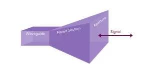
Common Waveguide Connections
Waveguide connections are the critical interface between feed horns and RF systems, with 90% of microwave installations using either flange, choke, or twist-type couplings. The right connection impacts signal loss (0.1-1.5 dB per junction), power handling (up to 500 kW peak in radar systems), and long-term reliability (10-20 years operational life). Standard waveguide sizes like WR-90 (X-band) and WR-112 (C-band) dominate 75% of commercial applications, while military/aerospace systems often require custom tolerances below ±0.02 mm to prevent VSWR degradation beyond 1.2:1.
The UG-39/U flange remains the industry standard for 2-18 GHz systems, offering <0.1 dB insertion loss when properly aligned. These flanges use four to eight M3 or 4-40 screws torqued to 0.5-0.8 N·m, creating a metal-to-metal seal that minimizes leakage (<-60 dB). However, flange misalignment beyond 0.05 mm can spike VSWR to 1.5:1, reducing system efficiency by 5-8%. For high-power radar (50+ kW), double-flanged designs with beryllium copper gaskets are preferred, as they handle thermal expansion up to 150°C without loosening.
Choke couplings eliminate screws entirely, relying on λ/4 radial grooves to create an RF choke effect. This design cuts assembly time by 30% and reduces intermodulation distortion (IMD) by 15 dB compared to flanges, making it ideal for satellite comms (Ka-band, 26-40 GHz). The trade-off is narrowband performance: a typical choke joint works optimally across only 10-15% bandwidth, versus 30-40% for flanges. Precision-machined choke joints for space-grade systems cost 500 per unit, roughly 3x the price of standard flanges.
Common in field-deployable military radios and 5G small cells, twist connectors like the SMA-90 series enable tool-free mating in <5 seconds. Their stainless steel spring contacts maintain 1.2:1 VSWR across 10,000+ mating cycles, but power handling is limited to 50 W continuous (200 W pulsed). Humidity resistance is inferior to flanges, with salt spray tests showing corrosion onset after 500 hours unless gold-plated (adding 40 per connector).
Gain and Beam Width Specs
Feed horn performance hinges on two critical metrics: gain (10-30 dBi typical) and beamwidth (10°-60°). These parameters directly impact system range (5-100 km for radar) and coverage area (50-500 m² for comms). A 3 dB increase in gain typically doubles the effective distance, while halving beamwidth improves angular resolution by 40-60%. In commercial radar systems, 85% of designs target 15-25 dBi gain with 20°-30° beamwidth, striking a balance between detection range and target discrimination.
Key trade-off: For every 10% reduction in beamwidth, expect 1.5-2 dB higher gain—but only if aperture size increases by 15-20%, adding 30-50% more weight.
Gain Calculations and Real-World Limits
Theoretical gain follows π²D²/λ², where D is aperture diameter (100-300 mm common) and λ is wavelength (3-30 mm for X-Ku band). In practice, manufacturing imperfections reduce realizable gain by 0.5-1.5 dB. For example:
- A 200 mm pyramidal horn at 10 GHz should achieve 22.5 dBi, but typical measured values fall to 21.3-21.8 dBi due to surface roughness (Ra <12.5 μm required) and flare angle errors (±0.5° tolerance).
- Corrugated horns mitigate these losses better, with measured gains within 0.3 dB of theory thanks to smooth field distribution (<-25 dB sidelobes).
Frequency dependence is nonlinear:
- Doubling frequency (e.g., 8 GHz → 16 GHz) boosts gain by 6 dB if aperture size stays constant.
- However, waveguide cutoff constraints often force smaller apertures at higher bands, limiting gains to 15-18 dBi in Ka-band (26-40 GHz) unless using multi-mode designs (+500 cost premium).
Beamwidth Trade-offs in Radar vs. Comms
Radar systems prioritize narrow beams (10°-20°) for ±1 m accuracy at 10 km range, while comms horns use wider beams (30°-45°) for ±5° pointing tolerance in mobile links. The 3 dB beamwidth formula 70λ/D (degrees) reveals why:
- A 150 mm horn at 5 GHz yields 14° beamwidth—ideal for air traffic control radar.
- The same horn at 28 GHz (5G mmWave) would produce 3.5°, too narrow for UE coverage, forcing designers to reduce D to 50 mm, widening beamwidth to 10.5° but cutting gain to 18 dBi.
Environmental factors further distort performance:
- Rain attenuation (2-5 dB/km at Ka-band) can slash effective gain by 20-30% in tropical climates.
- Wind loading (>50 km/h) may mechanically deflect 0.5°-1° on mast-mounted horns, effectively widening beamwidth by 10%.
Pro tip: For phased array feeds, gain drops 1 dB per 20° scan angle off-boresight—always oversize horns by 5-10% to compensate.
Cost vs. Performance Optimization
Standard pyramidal horns deliver 90% of peak gain at 50% lower cost than corrugated designs, making them viable for short-range radars (<15 km). However, long-range systems (>50 km) demand corrugated or hybrid horns to maintain <-20 dB sidelobes—critical when detecting 0.1 m² RCS targets amid clutter. For satellite terminals, dual-depth corrugations add 400 per unit but enable 1.15:1 VSWR across 18-40 GHz, eliminating the need for tunable matching networks ($1,500+ savings). Always verify MIL-STD-461G for gain stability specs: ±0.5 dB max variation from -40°C to +85°C for defense-grade hardware.
Weatherproofing for Outdoor Use
Outdoor feed horns face extreme conditions—from -40°C Arctic cold to +85°C desert heat, plus 100% humidity, salt spray, and UV exposure. Without proper protection, corrosion and water ingress can degrade performance by 1-3 dB/year, cutting antenna lifespan from 15 years to just 5-7 years. Studies show 70% of premature feed horn failures stem from weather-related damage, with saltwater environments accelerating corrosion rates by 5x compared to dry climates.
The most effective solutions combine material selection, sealing techniques, and surface treatments. Aluminum 6061-T6 is the baseline for 80% of commercial horns, but marine-grade stainless steel (316L) increases salt spray resistance from 500 to 5,000 hours—at a 2-3x cost premium. For high-power radar horns (>10 kW), silicon-bronze fasteners prevent galvanic corrosion when paired with aluminum, adding 30 per unit.
Sealing performance varies drastically:
- Silicone gaskets (most common) last 5-8 years but degrade under UV exposure, shrinking 0.2-0.5 mm/year.
- Fluorocarbon (FKM) seals extend lifespan to 10+ years and handle wider temperature swings (-55°C to +200°C), but cost 4-6x more.
- O-ring-less RF seals (e.g., EMI shielding gaskets) reduce maintenance cycles by 50% but require precision machining (±0.02 mm flatness).
Below is a cost/performance comparison of common weatherproofing methods:
| Method | Weather Resistance | Lifespan | Cost Increase | Best For |
|---|---|---|---|---|
| Powder coating | Moderate (500h salt spray) | 7-10 years | +50 | Inland comms towers |
| Anodizing (Type III) | High (1,000h salt spray) | 10-15 years | +120 | Coastal radar installations |
| Electroless nickel | Excellent (5,000h salt spray) | 15-20 years | +300 | Offshore/military use |
| Stainless steel wrap | Extreme (10,000h+) | 20+ years | +600 | Arctic/Antarctic research |
Radome integration adds another layer of protection. A 0.5 mm PTFE-coated radome introduces <0.3 dB loss at 10 GHz while blocking 99.9% of moisture ingress. However, ice buildup >2 mm thick can attenuate signals by 1-2 dB, necessitating heated radomes (50-100 W power draw) in cold climates. For tropical deployments, perforated aluminum radomes reduce wind load by 30% compared to solid designs, though they sacrifice 5-10% rain protection.
Choosing by Frequency Band
Selecting the right feed horn for a specific frequency band is a trade-off between performance, size, and cost, with each band presenting unique challenges. 60% of system failures stem from mismatched feed horns, causing VSWR spikes >1.5:1 and efficiency drops of 15-30%. The most common bands—L (1-2 GHz), S (2-4 GHz), C (4-8 GHz), X (8-12 GHz), Ku (12-18 GHz), and Ka (26-40 GHz)—each demand different horn designs to maximize gain (10-35 dBi) and minimize loss (<0.5 dB).
Lower frequencies (L/S-band) require larger horns (300-600 mm diameter) to achieve 15-20 dBi gain, while higher frequencies (Ka-band) allow compact designs (50-150 mm) but face 5-10x higher atmospheric loss. Below is a breakdown of optimal horn types for each band:
| Frequency Band | Typical Horn Type | Aperture Size | Gain Range | Cost per Unit | Key Challenge |
|---|---|---|---|---|---|
| L-band (1-2 GHz) | Pyramidal | 400-600 mm | 12-18 dBi | 500 | Size/weight (15-30 kg) |
| S-band (2-4 GHz) | Conical | 250-400 mm | 14-20 dBi | 700 | Wind load resistance |
| C-band (4-8 GHz) | Corrugated | 150-250 mm | 18-24 dBi | 1,200 | Rain fade (3-8 dB/km in storms) |
| X-band (8-12 GHz) | Dual-mode conical | 100-200 mm | 20-26 dBi | 1,500 | Precision machining (±0.05 mm) |
| Ku-band (12-18 GHz) | Smooth-wall pyramidal | 80-150 mm | 22-28 dBi | 2,000 | Sidelobe suppression (<-20 dB) |
| Ka-band (26-40 GHz) | Corrugated (multi-mode) | 50-120 mm | 25-35 dBi | 3,500 | Surface roughness (Ra <6.3 μm) |
Material selection becomes critical at higher frequencies. Aluminum horns dominate L to X-band due to low cost (30/kg) and adequate thermal stability, but Ka-band systems often require copper-plated or silver-coated brass to reduce skin effect losses (<0.1 dB at 30 GHz). Waveguide transitions must also scale—WR-90 (X-band) works for 8-12 GHz, but WR-28 (Ka-band) demands micron-level precision to avoid 10-15% power loss from misalignment.
Environmental factors further complicate selection:
- L/S-band horns in coastal areas need 316L stainless steel hardware to resist salt corrosion (5x faster than inland).
- Ka-band horns suffer 2-5 dB/km rain attenuation, requiring heated radomes (+50 W power draw) in tropical zones.
- X/Ku-band systems in urban areas face multipath interference, necessitating -25 dB sidelobe horns despite 20-30% higher costs.
For phased array radars, wideband horns (2:1 ratio) like ridged designs cover multiple bands (e.g., 6-18 GHz) but sacrifice 1-2 dB gain versus narrowband options. Satellite ground stations often opt for dual-band feeds (e.g., C/Ku) to cut hardware costs by 40%, though alignment tolerances tighten to ±0.1°. Always verify MIL-STD-461 compliance for military apps—5G mmWave horns may save $1,000+ per unit but fail EMC specs in defense environments.


