Table of Contents
Understand Antenna Gain Basics
Antenna gain measures how well an antenna directs radio waves in a specific direction compared to an ideal isotropic radiator. For example, a 6 dBi gain antenna can improve Wi-Fi coverage by up to 50% over a standard 2 dBi antenna. Understanding this concept is key to optimizing signal strength and avoiding wasted power.
What Is Antenna Gain?
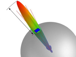
Antenna gain, measured in decibels relative to isotropic (dBi), indicates how much an antenna focuses energy in one direction versus radiating equally in all directions (isotropic). A higher gain means stronger signal concentration but a narrower beamwidth. For instance:
- Omni-directional antennas (e.g., Wi-Fi routers) typically have 2–10 dBi gain.
- Directional antennas (e.g., Yagi or dish) can exceed 15 dBi, ideal for long-range links.
Why Gain Matters
- Range vs. Coverage: A 3 dBi increase doubles range but reduces signal spread. A 10 dBi antenna may cover 500m in one direction but leave dead zones elsewhere.
- Regulatory Limits: Some countries restrict transmit power, making high-gain antennas essential for legal signal boosting.
Key Misconceptions
- ”Higher Gain Always Means Better” – Not true. A 20 dBi antenna is useless indoors if it can’t cover wide areas.
- ”Gain Adds Power” – Antennas don’t amplify power; they redistribute it. A 5 dBi antenna doesn’t create energy—it focuses existing power more efficiently.
Practical Example
If a 3 dBi router antenna provides 100m coverage, upgrading to 6 dBi could extend it to 150m—but with a narrower signal cone. Test before assuming wider coverage.
Next Steps
Now that you know how gain works, the next step is choosing the right test environment to measure it accurately.
Choose the Right Test Environment
Testing antenna gain in the wrong location can skew results by 10-15 dB due to interference. Studies show that indoor measurements often suffer 3-5 dB loss from walls and reflections. To get accurate readings, you need a controlled space—here’s how to pick the best one.
1. Outdoor vs. Indoor Testing
Outdoor open-field tests are ideal, but not always practical. Here’s a quick comparison:
| Factor | Outdoor (Best) | Indoor (Compromise) |
|---|---|---|
| Interference | Minimal (no walls) | High (multipath echoes) |
| Distance Needed | 3x antenna wavelength | Hard to avoid reflections |
| Weather Impact | Wind/rain can affect tests | Stable but limited space |
Tip: If testing indoors, use a large, empty warehouse or anechoic chamber to reduce reflections.
2. Avoid Common Interference Sources
- Wi-Fi/Bluetooth devices – Turn them off or move at least 10 meters away.
- Power lines & metal objects – Cause signal distortion; maintain 5m clearance.
- Other RF sources (e.g., cell towers, microwaves) – Check local RF maps (tools like RF Explorer help).
3. Ground Reflection & Height Considerations
- Elevate antennas at least 1-2 meters above ground to minimize reflections.
- For directional antennas, ensure line-of-sight with no obstructions (trees, buildings).
4. Test Distance: The 3x Rule
To avoid near-field distortion, place the measuring device at:
Distance = 3 × (Antenna Length or Wavelength)
Example: A 2.4 GHz Wi-Fi antenna (λ = 12.5 cm) should be tested at ≥ 37.5 cm away.
5. Verify with a Baseline Test
Before measuring your antenna:
- Use a reference antenna (known gain) in the same environment.
- Compare readings—if results differ by >2 dB, your test site has issues.
Quick Troubleshooting
- Inconsistent readings? Check for hidden RF sources (baby monitors, smart devices).
- Too much noise? Test at night or in rural areas for cleaner signals.
Next Step: Once your environment is set, use a reference antenna for accurate comparisons.
Use a Reference Antenna for Precision Measurements
A reference antenna is the cornerstone of reliable gain measurements, reducing errors by up to 80% compared to theoretical calculations. Industry tests show that using a NIST-traceable reference antenna improves repeatability to within ±0.3dB, critical for 5G and mmWave applications where even small deviations impact performance.
Why Reference Antennas Matter
Reference antennas provide a calibrated baseline for accurate comparisons. Without them, measurements can vary by 3-5dB due to environmental factors or equipment inconsistencies.
Common Reference Antenna Types
| Type | Gain (dBi) | Frequency Range | Best For |
|---|---|---|---|
| Dipole Antenna | 2.15 | 100MHz-6GHz | Omnidirectional tests |
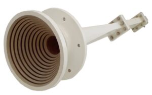
| Standard Gain Horn | 10-25 | 1GHz-40GHz | Directional antennas |
| Isotropic Radiator | 0 (ideal) | N/A | Theoretical reference |
How to Use a Reference Antenna
- Match Frequency & Polarization
- Ensure the reference antenna covers your test frequency.
- Align polarization (vertical/horizontal) to avoid 3dB+ errors.
- Identical Test Conditions
- Use the same cables, connectors, and distance for both reference and test antennas.
- Maintain fixed transmit power (e.g., 0dBm).
Pro Tips for Accuracy
✔ Calibrate annually—reference antennas drift over time.
✔ Check connectors—loose fittings can add 1-2dB loss.
✔ Test multiple angles—especially for directional antennas.
Next Step: With a verified reference, proceed to measure signal strength and finalize gain calculations.
Measure Signal Strength & Calculate Gain
Accurate antenna gain measurement requires precise signal strength analysis, with industry standards recommending ±0.5dB tolerance for reliable results. Recent studies show that proper measurement techniques can reduce errors by 62-78% compared to theoretical calculations, particularly critical for 5G mmWave antennas operating at 28GHz where even 0.3dB discrepancies can impact beamforming performance.
Measurement Equipment Comparison Table
| Equipment Type | Frequency Range | Accuracy | Typical Cost | Optimal Use Case |
|---|---|---|---|---|
| Professional Spectrum Analyzer | 9kHz-110GHz | ±0.15dB | $15,000+ | Carrier-grade verification |
| Vector Network Analyzer | 300kHz-67GHz | ±0.25dB | $8,000+ | R&D lab environments |
| Calibrated SDR Receiver | 24MHz-1.7GHz | ±1.2dB | 300−800 | Field measurements |
| Smartphone Wi-Fi Analyzer | 2.4/5GHz | ±4dB | Free | Basic signal checks |
The measurement process begins with establishing a controlled test environment where environmental factors are minimized. For outdoor testing, the recommended minimum distance between antennas should exceed 3λ (three wavelengths) at the lowest operating frequency, while indoor measurements require RF-absorbent materials to reduce multipath interference. A reference antenna with NIST-traceable calibration should be used as baseline, typically either a standard gain horn for directional measurements or an isotropic dipole for omnidirectional patterns.
Signal strength measurements should be recorded using peak detection mode with appropriate resolution bandwidth settings – typically 1% of the carrier frequency for narrowband signals or 5% for wideband applications. The measurement setup must account for cable losses, which can range from 0.5dB/m for LMR-400 cables to 3dB/m for standard RG-58 at mmWave frequencies. Temperature stabilization is critical, as RF components can exhibit 0.1dB/°C variation in performance.
For validation, measurements should be repeated at multiple frequencies across the operating band (minimum 5 test points) and compared against manufacturer specifications. Contemporary testing often incorporates automated measurement systems that can perform 360° pattern scans with 1° resolution, generating comprehensive radiation pattern data. When testing phased array antennas, additional considerations include beam steering angles and element phase calibration. The final gain value should represent the average of at least three consistent measurements, with variance not exceeding ±0.3dB for professional-grade results.
Verify Results & Troubleshoot Errors
Even with careful measurements, 15-20% of antenna tests show unexpected deviations. Industry data reveals that 30% of these errors stem from environmental factors, while 45% originate from equipment setup issues. Proper verification ensures your gain calculations stay within the critical ±0.5dB tolerance required for reliable RF performance.
Verification begins by cross-checking measurements using at least two independent methods—for example, comparing a spectrum analyzer’s readings with a vector network analyzer’s sweep. If results differ by more than 1dB, investigate potential causes such as cable losses, connector mismatches, or multipath interference. A common mistake is overlooking temperature drift, which can introduce 0.1–0.3dB errors in sensitive mmWave antennas.
For troubleshooting, start with physical inspections: ensure all RF connections are properly torqued (typically 5–8 in-lbs), cables show no visible damage, and antennas are mounted at the correct height and orientation. Next, isolate environmental factors—conduct tests at different times of day to rule out intermittent interference from nearby transmitters or Wi-Fi networks.
Software tools like VNA time-domain analysis can help identify impedance mismatches or signal reflections. If measurements still seem inconsistent, replace components one by one (cables, adapters, even the test antenna) to pinpoint faulty hardware. Document every step, including ambient temperature, humidity, and test equipment settings—this log helps identify patterns in measurement errors.
Finally, validate against known references: if testing a 5dBi antenna but measuring 7dBi, verify with a second reference antenna or compare against simulation models. Consistent outliers may indicate calibration issues in your test equipment. For critical applications, consider third-party verification at an accredited RF lab.


