Table of Contents
Component Selection
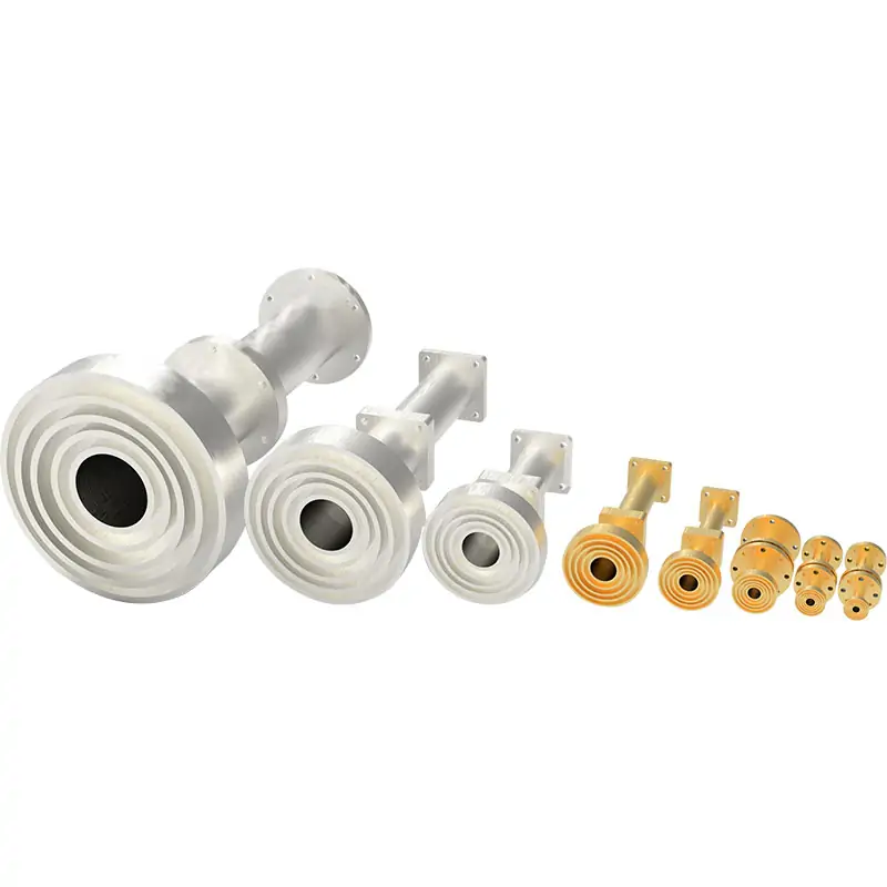
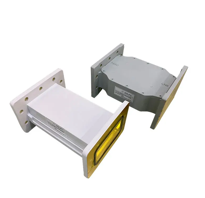
Choosing Multi-Band Feed Systems
Integrating multiple frequency bands into the antenna feed network requires the introduction of a multi-band feeding system, so the choice is to combine different frequency bands.
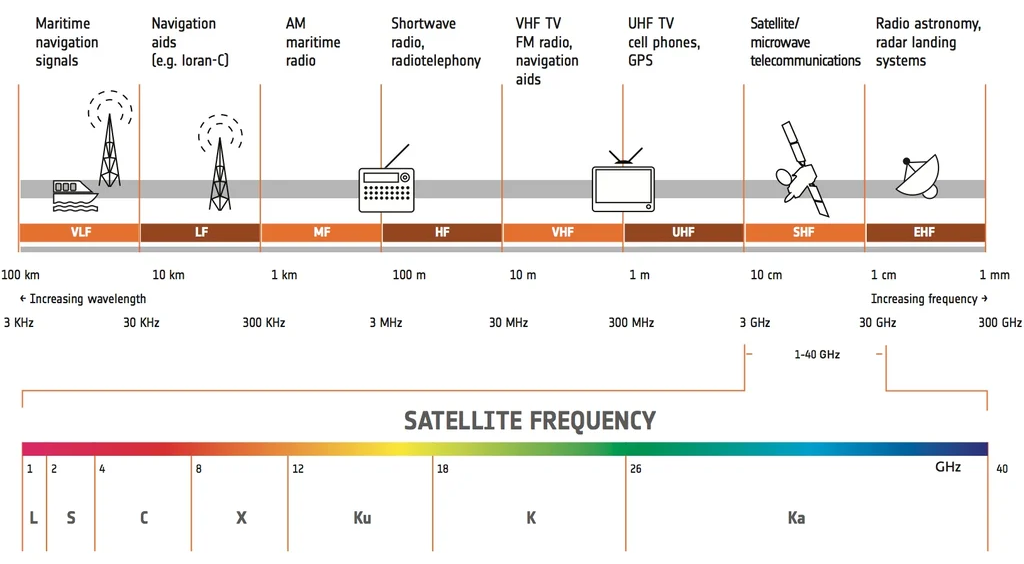
To determine the appropriate feed system, a list of frequency bands owned by the network needs to be compiled, which can be, for example, C-band, Ku-band and Ka-band or any other frequency range and combination thereof.
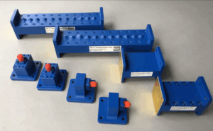
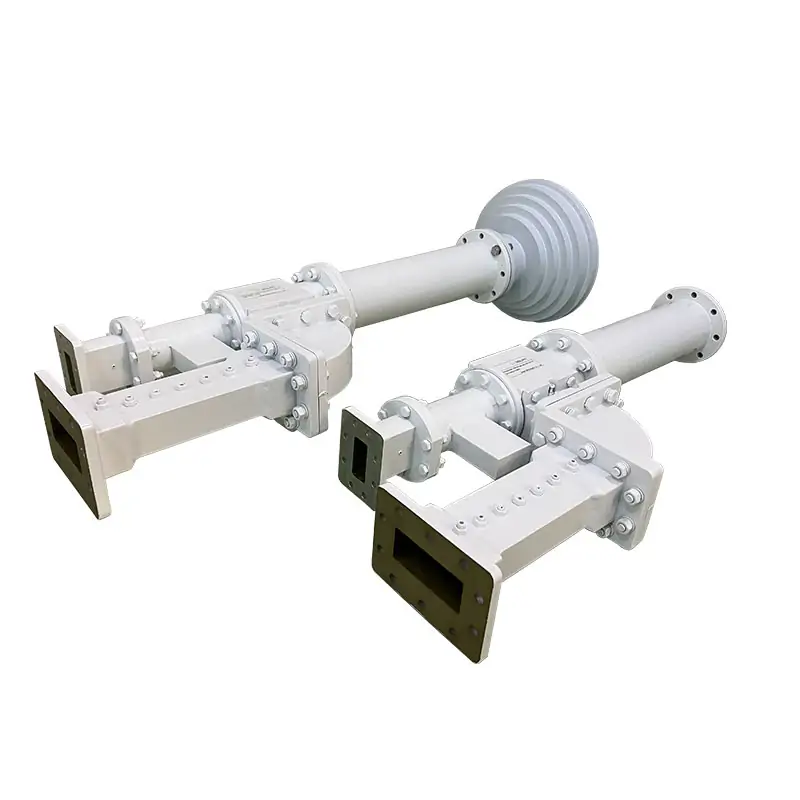
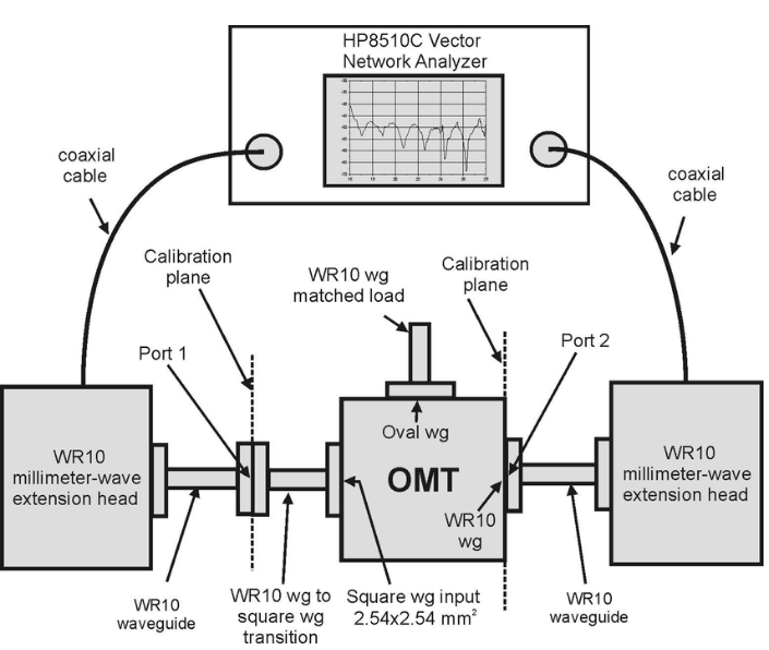
Selecting Filters and OMTs
Integrating multiple frequency bands into the antenna feed network also requires components to handle the frequency bands. Here, filters are selected for the frequency bands to be processed and an OMT is added to separate the signals based on their polarization (vertical and horizontal).
When selecting these components, refer to the appropriate range in the product data sheet. In addition, Dolph Microwave may prepare custom solutions in order to supply components that meet these demanding specifications.
Designing the network layout
In order to build multiple different frequency bands and minimize interference and losses to achieve an efficient and effective antenna feeding network and realize multiple frequency bands at the same time, the network layout should be designed. The network layout ensures that all components should be placed correctly to handle the frequency bands and no components conflict with each other.
Designing the physical location of all components in this way to make the signal path as short as possible and guide the signal path as much as possible is to plan and prevent failures in advance, otherwise there will be too many faults and damaged components during subsequent connection tests.At the same time, the most important point is to accurately record the data of each step.
Installation Steps
Mounting Multi-Band Feed Systems
Install the selected feed system at the intended location. To ensure optimal signal transmission and reception, be sure to use the necessary brackets and tools to stabilize the system and align it correctly.
It is important to note here that any deviation from the angle may result in considerable signal loss or attenuation. Therefore, refer to specific precision equipment such as laser pointers or alignment scopes to ensure that the feed system is aligned with the satellite or the area around the specific target.
Connecting Filters and OMTs
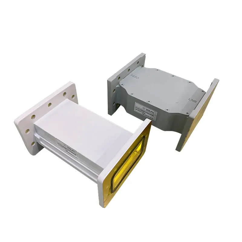
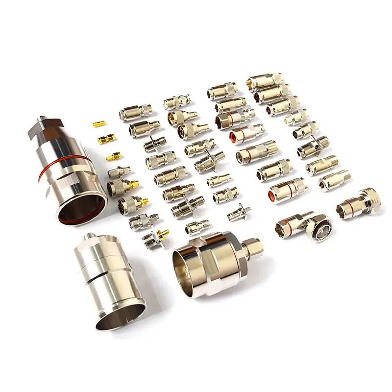
When connecting filters and orthogonal mode transducers into a network, it needs to be checked how the connections are made. They must be neither overly tight nor overly loose. Indeed, when the connection is too loose, it allows leakage of signals, as a result of which noise is generated, the signal is worsened.
It is required to use high-quality coaxial cables/waveguides to connect filters and OMTs. For example, waveguide diplexers are connected through high-precision waveguide flanges, so the loss is minimal, and the insulation is high.
Ensuring Proper Alignment
Proper alignment of the feed system, primarily through alignment of the carrier’s feed horn with the satellite or desired source, provides maximum signal reception and minimum interference.
Different alignment equipment, including inclinometers and azimuth and elevation indicators, can also be used to ensure precise placement.
Here, multiple frequency bands are integrated into the antenna feed network, and the rest is just calibration, testing, and performance optimization.
Calibration, Testing and Optimizing
Calibration Steps
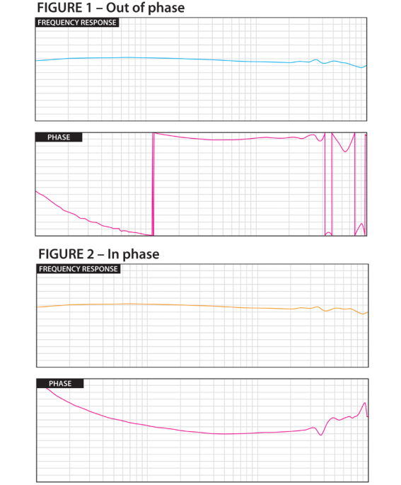
This is the initial calibration by adjusting each component of the system to make the frequency response as flat as possible in a specific range.
Next, insertion loss is minimized for signal integrity.
The final calibration is to perform S-parameter measurements, which mainly evaluate the reflection and transmission of the test.
Performance Testing
After calibration, you can verify network performance, which requires performance testing. For signal strength, you need to measure different points in the network to ensure coverage. Once the range is determined, the clarity will mostly be inconsistent, which requires checking for potential sources of interference and mitigating interference. At the same time, you have to test in different environments to ensure stable operation of all frequency bands.
Optimizing Performance
Now that the calibration results of the calibration and performance tests have been obtained, you can officially start on the work on performance optimization. In simple terms, it is necessary to make minor adjustments and changes to the system. For instance, you can try and adjust the physical position again of a few components, reduce the amount of interference, or alternatively increase the strength of the signal path. Settings can be changed as well such as the specified level of power, its distribution by channel, or the bandwidth allocation. In addition to that, there are also several strategies that you can test out in order to achieve maximum efficiency while carrying out the tests.