Table of Contents
Overview of Directional Couplers
Directional couplers are one of the most frequently used components in radio frequency systems that enable the measurement and diversion of power without disturbing the original signal flow. They are exceptionally accurate in distinguishing signal paths in terms of their direction of travel, which is essential for an array of purposes from signal sampling to the distribution of RF signals.
Definition
In RF and microwave engineering, a directional coupler can be defined as an essential tool that is used to sample a small portion of power going in one direction while excluding power that is moving in the opposite direction . This is determined by the physical design of the coupler, which typically consists of a main line and a coupled line. The effectiveness of a directional coupler is generally gauged via three key parameters, including the coupling factor, directivity, and isolation.
Parameters
The most widely used parameters include:
-
The coupling factor is a measure of the extent to which the direction of signal power is shifted from the main path to the coupled path, which is expressed in decibels on a logarithmic scale . The vast range typical for the function is between -20 dB and -30 dB, indicating that in 99% – 90% of cases, no more than 0.1% and 1% of power are sampled, respectively.
-
The optimum directivity of couplers is measured to be greater than 30 dB.
-
The isolation is a measure of the distance between the input and separated port, which is crucial for ensuring that excessive reflected power is used for measurement. The efficiency level of the coupler for this function is deemed to be higher than 20 dB.
How They Work
A directional coupler is effective due to the principle of electromagnetic coupling, which involves putting two near-field transmission lines in adjacent proximity . Mutually close transmission lines permit the shift of energy from one line to the second one. When used in both directions, the main signal remains unaffected while the sampled power is transmitted to the isolated port. The most frequently used applications include power monitoring, measurement of SWR, and signal distribution.
Applications
-
Antenna Feeding Networks Directional couplers are most widely applied in feeding networks for the distribution of power between antenna elements forming phased array systems.
-
Construction of Reflectometer Systems helps to measure the reflected power, which can serve as key data on the state of the antenna or transmission line.
-
Signal Sampling is widely used in power level detection tools or modulation analyzers.

Anatomy of a Directional Coupler
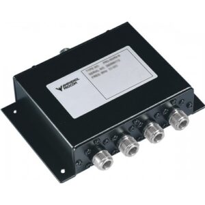
Directional couplers refer to sophisticated signal transmission and analysis devices. Their purpose is to separate signal paths and direct their paths depending on the direction of their waves. Each coupler is given four ports whose design varies, depending on the application. The four ports in a directional coupler include the Input, Output, Coupled, and Isolated ports. The direction of the signal in a coupler is from the Input to the Output, meaning that wave separation occurs based on signal propagation. The Input port is, thereby, the main entry or the initial port where the signal enters the coupler. The Output port is the exit of the signal after it passes through the coupler.
The Coupled port extracts a fraction of the signal power of the main Input–Output transmission. The Isolated port’s purpose is to absorb the reflected signal, preventing its return to the source. For the processes of direction from the signal source to its destination, the Input port is the main point of entry, while the Output port is the main exit point. The Coupled as well as the Isolated ports maintain their roles of monitoring and a framed point of reflection, respectively. The four ports in direction couplers are, thereby, useful and well-designed for these functions. There are a few other realizations, most being complex, but the defined applications are the most common.
Applications of each port in a directional coupler
Directional coupler’s four ports have different applications, with each playing a crucial role in their potency. The first and second ports in which the RF passes in and out are both crucial for its transmission. The Output port: This is the second coupler’s port that allows the continuation of the RF path. The Input port: This is where the RF source enters any coupler.
The coupled port: This is the third port that is useful in the coupler because of the extraction of a small fraction of its power P_c approximately 0.1P^2 , thereby, allowing its measurement. The Isolated port: This is the final port whose function is to absorb the entire reflected signal, and none of the coupler’s signal P .
Symmetry and port interchangeability
A noticeable feature of the couplers in the illustration is the symmetry of the first and second ports and that of the third and fourth ports. With this feature, the Input or Output coupler may interchange the two without causing any effect on impedance or function, especially in the cases of matched loads. There is no similar symmetry between the Input, Coupled, and Output and Isolated ports. The overall function of the coupler does change because the third and fourth ports must maintain their processes of extraction of reflection and absorption. Therefore, switching between these two middle and two terminal ports does not compromise the function of a coupler. The final two ports still follow the process of wave isolation, and the first two still carry the input signal for transfer without consequent wave extraction. These are some of the key features of the analyzed direction couplers and similar others.
Variants of Directional Couplers
Directional couplers, the basic RF devices that manipulate and analyze signals, are available in multiple designs, with various applications . The knowledge of coupler variants is necessary to choose the relevant device for a given RF system. To begin, one should understand the distinction between the 2-port and the 4-port types.
The main differences include:
Simplicity and specific uses. While 4-port couplers offer dual direction of coupling for simultaneous monitoring of both the forward and reverse signal, the 2-port type, also known as bi-directional coupler, operates in one direction, either forward or reverse. Such a design is particularly relevant for straightforward applications, where the understanding and adjustments of the signal in one direction are adequate . To a greater extent, such low-complexity designs are applicable in RF systems requiring simple signal sampling or line isolation.
Compatibility and isolation. For complex systems, where both the forward and reverse signal paths should be understood, including applications in reflection measurements or systems that require constant high isolation between the ports , 4-port types are more suitable. In this-in-a-Blue-Moon connection, it is also relevant to itemize the information that could be resolved only by the 4-port designs that employ dual direction of coupling .
The features of hybrid couplers, the subgroup of 4-port types, include:
The precise phase shift between the output signals at 90° for the quadrature hybrid or 180° for the rat-race coupler. This characteristic is relevant for phase-sensitive applications, such as beam-forming networks;
Equal power division. Balanced power splits are necessary for systems that require uniform signal distribution, such as antenna arrays.
Bi-directional types
The simple bi-directional couplers are described by the fundamental properties and offer dual direction of coupling, allowing the monitoring of both the forward and reflected power. Such types are applicable in the circuits where the data on the reflection and the knowledge of the return loss is necessary. Dual directional couplers, may be considered as a pair of two bi-directional couplers in one case . A real-time device for such uses may be relevant for specific applications where the real-time monitoring of signal paths in both directions is relevant for the system optimization and troubleshooting.
One could consider the advantages of the bi-directional type: simplicity, and the cost-effectiveness of a basic real-time monitoring of the power flow in one direction. The dual directional couplers are beneficial for complex diagnostic tasks that required are dual-directional simultaneous pre-calculated monitoring. It is reasonable to make a selection in light of the properties and requirements specific for the RF system in question.


